Are the motors TEFC? If there was a cooling issue shouldn't the motor shop have picked that up?We have no instrumentation to measure air flow. Good idea though.
You are using an out of date browser. It may not display this or other websites correctly.
You should upgrade or use an alternative browser.
You should upgrade or use an alternative browser.
Two speed one winding motor troubleshooting advice
- Thread starter phineascage
- Start date

- Status
- Not open for further replies.
phineascage
Member
- Location
- Gaffney, SC
Are the motors TEFC? If there was a cooling issue shouldn't the motor shop have picked that up?
Yes as stamped on the nameplate: TEFC.
Unless the fan is damaged or the fins are unusually dirty, the shaft mounted fan should provide rated cooling. But that doesn't address the excessive current.Yes as stamped on the nameplate: TEFC.
I'm still with it being a motor fault. And I'm still of the opinion that 152A no-load current is excessive despite what the motor shop claims.
phineascage
Member
- Location
- Gaffney, SC
are the fan blades adjustable pitch?
No they are fixed.
kwired
Electron manager
- Location
- NE Nebraska
I think voltage at motor end of the circuit is important to knowI have not measured actual voltage on our two other normally functioning fan motors. I tend to believe though that the voltage at each of their respective output contactors is roughly 480 on all phases since they are fed from the same MCC as our problem motor.
I wish I could find a voltage drop, I could stop scratching my head.
I think he meant the driven load....Not on a TEFC.
But we keep getting posts that ignore that fact.Thought we had put than one to bed.
The current difference is seen uncoupled.
And that's not very helpful.I think voltage at motor end of the circuit is important to know
I think he meant the driven load....
But we keep getting posts that ignore that fact.
phineascage
Member
- Location
- Gaffney, SC
I think voltage at motor end of the circuit is important to know
I think he meant the driven load....
But we keep getting posts that ignore that fact.
Voltage at the motor end on the problem motor was measured. It was roughly 476VAC. All balanced.
GeorgeB
ElectroHydraulics engineer (retired)
- Location
- Greenville SC
- Occupation
- Retired
Whilst true, the OP has observed a 45A current difference with the motor uncoupled so unrelated to the gearbox.
In my world, electrohydraulics, a flat mounting surface and uniform proper torque (yeah, torque, I know) are necessary. A non-planar surface or significantly uneven torque will affect internal clearances to the point that sticking will occur.
On the test bench, all is fine. Installed, current is high and at least one bearing has failed.
Given all the great postings here, I'd check that the mounting surface is in a plane. The motor frame COULD be so distorted that abnormal bearing loads impose additional friction/loads.
Good points if I may say so, sir....In my world, electrohydraulics, a flat mounting surface and uniform proper torque (yeah, torque, I know) are necessary. A non-planar surface or significantly uneven torque will affect internal clearances to the point that sticking will occur.
On the test bench, all is fine. Installed, current is high and at least one bearing has failed.
Given all the great postings here, I'd check that the mounting surface is in a plane. The motor frame COULD be so distorted that abnormal bearing loads impose additional friction/loads.
")
I wouldn't rule out a distorted motor frame causing a problem and, as you rightly point out, there has been a bearing failure in the past. That, if I recall correctly, is what got the motor to the repair shop in the first place. But I'm inclined to think that the amount of force to distort the frame might snap the feet off especially if it is a cast iron frame which is often the case.
And that still leaves the 152A measured on the shop test. Interesting problem, not that it helps the OP. It will be interesting to see what is concluded/discovered when the motor goes back to the shop.
phineascage
Member
- Location
- Gaffney, SC
Good points if I may say so, sir....
I wouldn't rule out a distorted motor frame causing a problem and, as you rightly point out, there has been a bearing failure in the past. That, if I recall correctly, is what got the motor to the repair shop in the first place. But I'm inclined to think that the amount of force to distort the frame might snap the feet off especially if it is a cast iron frame which is often the case.
And that still leaves the 152A measured on the shop test. Interesting problem, not that it helps the OP. It will be interesting to see what is concluded/discovered when the motor goes back to the shop.
Thank you all for the great troubleshooting advice. When I eventually get to the bottom of this problem I will post back here with the resolution.
Don't worry!Thank you all for the great troubleshooting advice. When I eventually get to the bottom of this problem I will post back here with the resolution.
We will hound you until you do!!!
kwired
Electron manager
- Location
- NE Nebraska
A motor as large as what OP has probably doesn't distort too easily either, but at same time probably not impossible and deserves some consideration.Good points if I may say so, sir....
I wouldn't rule out a distorted motor frame causing a problem and, as you rightly point out, there has been a bearing failure in the past. That, if I recall correctly, is what got the motor to the repair shop in the first place. But I'm inclined to think that the amount of force to distort the frame might snap the feet off especially if it is a cast iron frame which is often the case.
And that still leaves the 152A measured on the shop test. Interesting problem, not that it helps the OP. It will be interesting to see what is concluded/discovered when the motor goes back to the shop.
Russs57
Senior Member
- Location
- Miami, Florida, USA
- Occupation
- Maintenance Engineer
If I was in your shoes I would eliminate as many things as possible.
For example remove wiring, at motor, for T1, T2, and T3 and connect motor leads together there. Go back to high speed starter and directly connect L1 to T6 and so on. This way you are eliminating all starters and the smaller gauge wiring which short T1, T2, and T3 together. Might also loosen hold down bolts and check with feeler gauge to see if mounting plate is flat. I would have driveshaft off.
A few Polaris taps and a couple of feet of wire should suffice for a quick experiment. I’ll assume you have suitable OCP to allow such an experiment to be done safely.
Given the long term nature and the critical nature of the load I’d want a spare motor on hand anyway so maybe best to buy a new one and put reconditioned motor on the shelf.
phineascage
Member
- Location
- Gaffney, SC
If I was in your shoes I would eliminate as many things as possible.
For example remove wiring, at motor, for T1, T2, and T3 and connect motor leads together there. Go back to high speed starter and directly connect L1 to T6 and so on. This way you are eliminating all starters and the smaller gauge wiring which short T1, T2, and T3 together. Might also loosen hold down bolts and check with feeler gauge to see if mounting plate is flat. I would have driveshaft off.
A few Polaris taps and a couple of feet of wire should suffice for a quick experiment. I’ll assume you have suitable OCP to allow such an experiment to be done safely.
Given the long term nature and the critical nature of the load I’d want a spare motor on hand anyway so maybe best to buy a new one and put reconditioned motor on the shelf.
Good idea. As soon as I can get some materials to do this with I will.
We're discussing a spare motor. It's an incredibly pricey animal though but looks like we definitely need one.
- Location
- San Francisco Bay Area, CA, USA
- Occupation
- Electrical Engineer
Someone in another forum questioned the conductor size (#2) on the shorting circuit that goes to the 3rd contact, connected to 1, 2 &3. the contactor is supposed to be sized for a minimum of 50% of the current rating of the other contactors, because it is the Y point for half of the circuit (in high speed, it is two parallel Y winding sets, one set is already connected, the contactor connects the others). So with the FLA rating of the motor requiring 500MCM cable, the shorting circuit conductors should have been a minimum of 3/0, maybe 4/0 with VD. My thought is that someone erroneously sized those conductors for the Low Speed current, but in Low, those conductors don't even carry current. So what I think is happening is that the under sized conductors are creating a VD in that half of the 2Y windings, evidenced by the fact that the two sets of windings are not showing the same current, and they should be.

kwired
Electron manager
- Location
- NE Nebraska
I was a little curious how this motor worked on each speed.Someone in another forum questioned the conductor size (#2) on the shorting circuit that goes to the 3rd contact, connected to 1, 2 &3. the contactor is supposed to be sized for a minimum of 50% of the current rating of the other contactors, because it is the Y point for half of the circuit (in high speed, it is two parallel Y winding sets, one set is already connected, the contactor connects the others). So with the FLA rating of the motor requiring 500MCM cable, the shorting circuit conductors should have been a minimum of 3/0, maybe 4/0 with VD. My thought is that someone erroneously sized those conductors for the Low Speed current, but in Low, those conductors don't even carry current. So what I think is happening is that the under sized conductors are creating a VD in that half of the 2Y windings, evidenced by the fact that the two sets of windings are not showing the same current, and they should be.
View attachment 20365
That should put 277 volts across each "coil" when in the "B" configuration and 138.5 volts across same coils when in "A" configuration. I guess what surprises me a little is that it can take that much voltage difference across the same coil, but maybe as long as driving a variable torque load you get away with that easier then with a constant torque load.
It seems they are just starving the coils for voltage when in low speed configuration and therefore less torque is produced and more slip occurs. Seems that nameplate low speed would only occur when driven load is at the low speed rating. Uncoupling the load completely would likely make it run much closer to high speed rating only load in that case is what it takes to keep the rotor itself turning, and it should be able to come much closer to synchronous speed with no external load applied. That said the rotor on a 250 HP motor is still going to take somewhat significant power to spin it compared to say the rotor of a 10 HP motor.
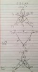
this is how I thought a 2s1w worked
basically a split winding per phase
lo the windings are in series and form a delta
hi the windings are in parallel and form a wye
the lo contactor c1 carrys 100 a
the hi contactor c2 carries fla 290
the hi shorting contactor carries fla also (center of wye)
basically a split winding per phase
lo the windings are in series and form a delta
hi the windings are in parallel and form a wye
the lo contactor c1 carrys 100 a
the hi contactor c2 carries fla 290
the hi shorting contactor carries fla also (center of wye)
Attachments
kwired
Electron manager
- Location
- NE Nebraska
this is how I thought a 2s1w worked
basically a split winding per phase
lo the windings are in series and form a delta
hi the windings are in parallel and form a wye
the lo contactor c1 carrys 100 a
the hi contactor c2 carries fla 290
the hi shorting contactor carries fla also (center of wye)
Too small for me to read, enlarged your drawing to 250% but still a little hard to decipher some things because of poor resulution at that magnification.
But looks to me like when connected in delta each winding sees 240 volts across it. When in the parallel wye - same windings each see 277 volts across them. Wouldn't that give you close to same overall output, sort of like difference in applying 208 or 240 to a 208-240 volt motor, one will draw a little more current but speed and horsepower will otherwise be nearly the same.
- Status
- Not open for further replies.