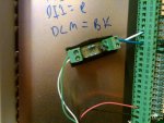
The pictures are of a Dura Pulse drive. The speed reference is going into ACM & AI1 terminals on the drive, but first the wires are going through this homemade board. Any ideas on what this is doing and why??? Thanks!!!
You are using an out of date browser. It may not display this or other websites correctly.
You should upgrade or use an alternative browser.
You should upgrade or use an alternative browser.
VFD Question What is this doing???
- Thread starter C3PO
- Start date
- Status
- Not open for further replies.
- Location
- San Francisco Bay Area, CA, USA
- Occupation
- Electrical Engineer
At first I was thinking it's probably converting from a current reference signal to a voltage reference input, i.e. 4-20ma to 0-10VDC because AI1 is the 10VDC speed reference signal input. But that only really takes a resistor and this has at least 2 resistors plus a cap. Besides, if they wanted to use the 4-20ma all they had to do was terminate on AI2. Maybe there's an opto isolator on the back of that breadboard? They may just be isolating the signal so no noise gets into the VFD. Kind of an odd way to do it though.
At first I was thinking it's probably converting from a current reference signal to a voltage reference input, i.e. 4-20ma to 0-10VDC because AI1 is the 10VDC speed reference signal input. But that only really takes a resistor and this has at least 2 resistors plus a cap. Besides, if they wanted to use the 4-20ma all they had to do was terminate on AI2.
That was my first thought as well. Not sure what it is doing.
- Location
- San Francisco Bay Area, CA, USA
- Occupation
- Electrical Engineer
Well that's what a PI or PID loop is for, or even the accel/decel rate programming. But I suppose if someone didn't know that they could have tried to do it externally.My WAG is a low pass filter to reduce any fast changes in the input signal. It would keep the VFD from making any fast changes in output speed.
What's the input from, and what is is driving??
ATSman
ATSman
- Location
- San Francisco Bay Area
- Occupation
- Electrical Engineer/ Electrical Testing & Controls
MOV maybe
MOV maybe
I have seen a resistor and cap in series connected across an automatic transfer switch solenoid coil to disipate the inductive kick when the coil switches the main contacts. This acts the same as an MOV (metal oxide varistor) to absorb the back EMF of the coil when the field collapses. The input to the coil is usually fed from the DC terminals of a bridge rectifier since DC provides a stronger pull than AC.
In this case, the intent may be to limit the input voltage spikes to an acceptable level.
Just a thought.
gar
Senior Member
- Location
- Ann Arbor, Michigan
- Occupation
- EE
110527-1246 EDT
My guess is that red and black are a power source to the device at the end of the cable. This might be as simple as a potentiometer. It appears there are two 5.6 K resistors. and possibly a 25 to 100 mfd capacitor.
Seems pretty clear it is a filter or averaging circuit. Probably to reduce noise. If the input is a differential amplifier I can see a resistor in both input leads. But then it might be desirable to have a capacitor from each input to ground which I might expect is the black wire.
More needs to be known about what is at the end of the wire.
I am not familiar with the motor control and therefore what the various terminals are.
.
110527-1246 EDT
My guess is that red and black are a power source to the device at the end of the cable. This might be as simple as a potentiometer. It appears there are two 5.6 K resistors. and possibly a 25 to 100 mfd capacitor.
Seems pretty clear it is a filter or averaging circuit. Probably to reduce noise. If the input is a differential amplifier I can see a resistor in both input leads. But then it might be desirable to have a capacitor from each input to ground which I might expect is the black wire.
More needs to be known about what is at the end of the wire.
I am not familiar with the motor control and therefore what the various terminals are.
.
They look like 1 Kohm resistors to me. Brown, Black, Black, Red. The lower one might have an orange multiplier, so it might be 10K. Hard to tell from the photo.
110527-1246 EDT
My guess is that red and black are a power source to the device at the end of the cable. This might be as simple as a potentiometer. It appears there are two 5.6 K resistors. and possibly a 25 to 100 mfd capacitor.
Seems pretty clear it is a filter or averaging circuit. Probably to reduce noise. If the input is a differential amplifier I can see a resistor in both input leads. But then it might be desirable to have a capacitor from each input to ground which I might expect is the black wire.
More needs to be known about what is at the end of the wire.
I am not familiar with the motor control and therefore what the various terminals are.
.
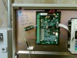
The wire runs to a DAQ which is controlled by a computer program. The red and black wires you see are giving the drive the start/stop command. The wires that come out of the breadboard are tied into the speed reference. AI1 is 0 to 10V input only
110527-1246 EDT
My guess is that red and black are a power source to the device at the end of the cable. This might be as simple as a potentiometer. It appears there are two 5.6 K resistors. and possibly a 25 to 100 mfd capacitor.
Seems pretty clear it is a filter or averaging circuit. Probably to reduce noise.
I agree. A filter. The electrolytic capacitor and relatively high value resistors suggest a DC signal. The implementation looks like an amateurish bodge to fix a field problem.
gar
Senior Member
- Location
- Ann Arbor, Michigan
- Occupation
- EE
110527-1719 EDT
steve66:
It is really hard to tell with the photo resolution. I read the colors as green, blue, red, and silver. I sort of worked back from silver and red (now I think red is orange) and tried to visualize the spacer bands. I think an AB (Ohmite) would have been easier to read. Whatever the resistance it is only a bandwidth factor.
C3PO:
So if AI1 is the speed command what is it referenced to? I suspect it is ACM. If so, then is ACM tied to the power system EGC?
At the DAC end I have to assume it is the voltage source and probably referenced to its own EGC. If this is the setup, then there are big ground noise problems.
My suggestion of an appropriate setup would be:
(1) Use of an isolated DAC. Meaning DC isolation between the digital input and the analog output, likely optical couplers.
(2) The 10 V supply to feed the DAC would be from the 10 V supply in the drive.
(3) The DAC would still be near the computer and one would still use the low pass filter at the drive, but only one resistor. No resistor would be in the common reference line between the DAC and the drive.
(4) Probably put a 25 mfd capacitor at the DAC across the 10 V supplied to it.
These two references give some information on an isolated DAC. This DAC has an internally generated voltage for the DAC divider.
http://www.analog.com/static/imported-files/circuit_notes/CN0065.pdf
http://www.analog.com/static/imported-files/data_sheets/AD5412_5422.pdf
If you search around there are probably a number of isolated DAC schemes.
.
I agree. A filter. The electrolytic capacitor and relatively high value resistors suggest a DC signal. The implementation looks like an amateurish bodge to fix a field problem.
What kind of field problem do you think would need that?
- Location
- San Francisco Bay Area, CA, USA
- Occupation
- Electrical Engineer
Most likely the 1-10VDC signal they are sending to the VFD is picking up noise from somewhere and rather than fix that problem by seeing what they did wrong (i.e. bad shielding practices, running signal wires in the same conduit as power wires etc. etc.) they chose to deal with the symptom.
gar
Senior Member
- Location
- Ann Arbor, Michigan
- Occupation
- EE
110528-1242 EDT
A ground path noise problem. Especially a DC voltage on the ground path and the filter will do nothing about that.
The magnitude of non-ground path or ground path noise could be a problem, it could saturate the input amplifier in the motor control, or just cause errors.
The frequency of input noise could be a problem.
Problems could produce undesired function of the motor control.
Does the system do what it is expected to do, or are there deviations?
Some motor controls create a lot of noise. I had one customer with two nearly identical HAAS CNC machines. There was about a one year difference in manufacturing date between the two. One machine had DC servos, and the newer one had brushless servos. With the newer machine it was impossible to do RS-232 communication with that machine from a remote computer when the servos were on. This meant drip feeding was impossible. Installation of our I232 isolators broke the ground path loop and solved the problem.
.
You all were right on the money with your guesses. I was finally able to get ahold of the people that built this. This is what they told me "The 'device' is a low pass filter. (see attachment) Without it the DAQ system receives feedback from the analog output and corrupts the DAQ."
This piece of equipment is new ( we have had it for less then two months) it appears to be functioning the way it is supposed to, but when the VFD's on this stand are running it puts noise on pressure transducers that are on another piece of equipment that is fed from the same panel as this stand but about 50' away from this equipment.
I was debating on changing the VFD's(most likely to ATV71s) to a more reputable brand and putting line reactors in front of them.
Do you think changing the drives and adding line reactors will fix the problem or should I do something else?
Also if I do change the drives will I still need the homemade "filter" on the speed reference?
Thanks for all the input!!!
gar
Senior Member
- Location
- Ann Arbor, Michigan
- Occupation
- EE
110528-1926 EDT
C3PO:
I do not think the DAQ is being corrupted. Rather more likely the output or input from or to the DAQ is being corrupted. Most likely the output. My previous suggestion of an isolated DAQ at the computer and a revised filter at the motor control is where I would start, because this is a necessary revision.
Your pressure sensor problem requires more information. Both from the DAQ problem and the pressure sensor problem it seems like little thought was given to avoiding noise problems.
It is always necessary to look for ground path problems, and inductive and capacitive coupling of noise.
Are the pressure transducers of the bonded straingage type, or something else? What is the input excitation to the transducers? What is the output signal level of the transducer itself? How are these wired and grounded? What is the required accuracy and resolution? What is the magnitude, percentage of full scale, of the noise? What is the frequency spectrum of the noise? Can filtering solve the problem? Do the pressure transducers provide signals to the same computer that is connected to the motor drive?
.
gar
Senior Member
- Location
- Ann Arbor, Michigan
- Occupation
- EE
110530-1329 EDT
C3PO:
Also find out what response time is required from the pressure transducers. Is it a few milliseconds, or many seconds?
.
C3PO:
Also find out what response time is required from the pressure transducers. Is it a few milliseconds, or many seconds?
.
110527-1719 EDT
steve66:
It is really hard to tell with the photo resolution. I read the colors as green, blue, red, and silver. I sort of worked back from silver and red (now I think red is orange) and tried to visualize the spacer bands. I think an AB (Ohmite) would have been easier to read. Whatever the resistance it is only a bandwidth factor..
To answer some of the ealrier questions. After getting more info, the resistors are 10K ohm and the cap is 1micro farad.
C3PO:
So if AI1 is the speed command what is it referenced to? I suspect it is ACM. If so, then is ACM tied to the power system EGC?
At the DAC end I have to assume it is the voltage source and probably referenced to its own EGC. If this is the setup, then there are big ground noise problems..
You are correct ACM. It is not tied to the EGC on the drive end anyway. It could be on the DAQ end. You are also correct that the voltage source for the speed ref is at the DAQ end.
So do you all think that the "low pass filter" was put in because of noise created by the drive itself or from something else??
I know the "filter was already installed before the stand was shipped to us.
If a different drive was used do you think the filter would be needed?
The trandsducer is a Validyne DP15-52 a shielded cable (at one end) runs from it into a Validyne CD280-4-1529, then from there a shielded cable to a Tektronix DPO2014 Oscilloscope
http://www.validyne.com/Productdisplay.aspx?Pid=12
http://www.validyne.com/ProductDisplay.aspx?Pid=27
The only thing the two pieces of equipment have in common is that they are fed from the same I Line Panel. I believe the response time from the transducers is pretty fast.
http://www.validyne.com/Productdisplay.aspx?Pid=12
http://www.validyne.com/ProductDisplay.aspx?Pid=27
The only thing the two pieces of equipment have in common is that they are fed from the same I Line Panel. I believe the response time from the transducers is pretty fast.
- Status
- Not open for further replies.