Am currently designing a separately derived system for the interior of a building, 480/208Y transformer feeding a lighting panel located greater than 75 ft. away, thus requiring secondary conductor protection (breaker in this case) near the transformer per 240.4(F) in conjunction with 240.21(C). Conduit system is EMT. Grounding electrode conductor connection to neutral is in transformer, thus requiring the system bonding jumper connection at the same point. My question is: if I run what I would consider to be the system bonding jumper from the panel ground bus back thru the secondary breaker to the transformer neutral, am I allowed to terminate in the breaker and then continue on with another piece of wire to the transformer neutral? Would this violate the 250.30(A)(1) statement "An unspliced system bonding jumper ...."? Or, can the conductor from the panel ground bus to the breaker ground connection be considered part of the equipment grounding conductor system, in which case the conductor from the breaker ground connection to the transformer neutral could be considered to be the "unspliced system bonding jumper"? Appreciate any help.
You are using an out of date browser. It may not display this or other websites correctly.
You should upgrade or use an alternative browser.
You should upgrade or use an alternative browser.
System Bonding Jumper Configuration on Separately Derived System with Secondary OCPD
- Thread starter bozo
- Start date
- Status
- Not open for further replies.
I think there is a small terminology flaw that may be tricking you. The system bonding jumper is the wire that connects the grounding conductors to the grounded conductor and you are doing that at the transformer.
You would then have an equipment bonding jumper to your first disconnect. See 250.30(A)(2). Once you leave your first disconnect on the way to your panel it is simply and equipment grounding conductor.
The system bonding jumper (at the transformer) and the equipment bonding jumper to the 1st disconnect is sized per 250.66 based on the size of the phase conductors. The GEC will be sized per 250.122 (if a conductor is used)
ivsenroute
Senior Member
- Location
- Florida
Don't forget to bond the cold water pipe and structural steel in the area that the separately derived system services.
Your last sentence should be: The EGC will be sized per 250.122 (if a wire-type EGC is used).I think there is a small terminology flaw that may be tricking you. The system bonding jumper is the wire that connects the grounding conductors to the grounded conductor and you are doing that at the transformer.
You would then have an equipment bonding jumper to your first disconnect. See 250.30(A)(2). Once you leave your first disconnect on the way to your panel it is simply and equipment grounding conductor.
The system bonding jumper (at the transformer) and the equipment bonding jumper to the 1st disconnect is sized per 250.66 based on the size of the phase conductors. The GEC will be sized per 250.122 (if a conductor is used)
The system bonding jumper is the wire that connects the grounding conductors to the grounded conductor and you are doing that at the transformer.
You would then have an equipment bonding jumper to your first disconnect. See 250.30(A)(2).
Thanks for the reply. I think we agree that one end of the system bonding jumper should be terminated at the transformer neutral (in this situation). Are you saying the other end should terminate at the ground terminal or bus of the secondary breaker (first system disconnect)? This would appear to make sense. Like you said, from that point on it could just be considered part of the EGC system.
Also, just to be clear, in your last statement "The GEC will be sized per 250.122 (if a conductor is used)" did you mean to say EGC (equipment grounding conductor) instead of GEC (grounding electrode conductor)?
Thanks again.
The system bonding jumper, according to 250.30(A)(1) can be at the transformer or at the first disconnecting means. In your original post you indicated your grounding electrode conductors and system bonding jumper were at the transformer. That being the case, an equipment bonding jumper should be routed to the first disconnect (see 250.30(A)(2).
And, as Smart$ pointed out, the old man's typing finger-brain tricked him again and the "GEC" in the last sentence should be "EGC"
And, as Smart$ pointed out, the old man's typing finger-brain tricked him again and the "GEC" in the last sentence should be "EGC"
Both ends of the system bonding jumper terminate in the same piece of equipment or enclosure.Thanks for the reply. I think we agree that one end of the system bonding jumper should be terminated at the transformer neutral (in this situation). Are you saying the other end should terminate at the ground terminal or bus of the secondary breaker (first system disconnect)? This would appear to make sense. Like you said, from that point on it could just be considered part of the EGC system.
The grounding conductor between the transformer and first disconnecting means is called an equipment bonding jumper. This term differentiates it from an equipmnet grounding conductor in that it is run with conductors considered to have no overcurrent protection, such as transformer secondary tap conductors.
Past the first disconnecting means, the grounding conductors are equipment grounding conductors.
hurk27
Senior Member
- Location
- Portage, Indiana NEC: 2008
I just want to see how he designs a 480/208Y transformer
Not sure if you're referring to my choice of terminology "Am currently designing a separately derived system" or something else (like maybe my intelligence). If the terminology above was what you were referring to, it seems appropriate as defined in the code ("Separately Derived System. A premises wiring system whose power is derived from a source of electric energy or equipment other than a service. Such systems have no direct electrical connection, including a solidly connected grounded circuit conductor, to supply conductors originating in another system.")I just want to see how he designs a 480/208Y transformer
Both ends of the system bonding jumper terminate in the same piece of equipment or enclosure.
The grounding conductor between the transformer and first disconnecting means is called an equipment bonding jumper. This term differentiates it from an equipmnet grounding conductor in that it is run with conductors considered to have no overcurrent protection, such as transformer secondary tap conductors.
Past the first disconnecting means, the grounding conductors are equipment grounding conductors.
First of all, thanks for the input. Exhibit 250.13 ("A grounding arrangement for a separately derived system in which the grounding electrode conductor connection is made at the transformer") on page 199 of the 2005 NEC Handbook appears to clearly disagree with your statement about both ends terminating in the same piece of equipment. This diagram clearly indicates one end of the system bonding jumper terminating at the transformer neutral and the other end terminating at the ground bus in the first system disconnect enclosure. This is the only ground conductor shown connecting the two enclosures (there is no mention of any bonding via the conduit between the two). The equipment bonding jumper in this diagram connects the transformer neutral to the transformer enclosure. Is this diagram incorrect?
Also, are you saying that the system bonding jumper connects the transformer neutral to the transformer ground, and then the equipment bonding jumper connects the transformer ground to the first system disconnect ground? If this is true, then why does Art. 250.30(A)(1) not mention that the system bonding jumper connects the equipment grounding conductors to the grounded conductor via the equipment bonding jumper?
From your description of the diagram, yes, it is incorrect. I recall someone posting such a diagram awhile ago having the same configuration, and it too was incorrect... perhaps it was the same diagram.First of all, thanks for the input. Exhibit 250.13 ("A grounding arrangement for a separately derived system in which the grounding electrode conductor connection is made at the transformer") on page 199 of the 2005 NEC Handbook appears to clearly disagree with your statement about both ends terminating in the same piece of equipment. This diagram clearly indicates one end of the system bonding jumper terminating at the transformer neutral and the other end terminating at the ground bus in the first system disconnect enclosure. This is the only ground conductor shown connecting the two enclosures (there is no mention of any bonding via the conduit between the two). The equipment bonding jumper in this diagram connects the transformer neutral to the transformer enclosure. Is this diagram incorrect?
Also, are you saying that the system bonding jumper connects the transformer neutral to the transformer ground, and then the equipment bonding jumper connects the transformer ground to the first system disconnect ground? If this is true, then why does Art. 250.30(A)(1) not mention that the system bonding jumper connects the equipment grounding conductors to the grounded conductor via the equipment bonding jumper?
If it stands as proposed, this issue will be clarified in the 2011 NEC:
[Text underlining and color emphasis above by me](1) System Bonding Jumper. An unspliced system bonding
jumper shall be installed. It shall be sized in compliance
with 250.28(A) through (D). This connection shall be made
at any single point on the separately derived system from
the source to the first system disconnecting means or overcurrent
device, or it shall be made at the source of a separately
derived system that has no disconnecting means or
overcurrent devices, in accordance with (a) or (b). If the
source is located outside the building or structure supplied,
a system bonding jumper shall be installed at the grounding
electrode connection in compliance with (C). [ROP 5-102]
Exception No. 1: For systems installed in accordance with
450.6, a single system bonding jumper connection to the tie
point of the grounded circuit conductors from each power
source shall be permitted. [ROP 5-102]
Exception No. 2: A system bonding jumper at both the
source and the first disconnecting means shall be permitted
if doing so does not establish a parallel path for the
grounded conductor. If a grounded conductor is used in this
manner, it shall not be smaller than the size specified for
the system bonding jumper but shall not be required to be
larger than the ungrounded conductor(s). For the purposes
of this exception, connection through the earth shall not be
considered as providing a parallel path.
Exception No. 3: The size of the system bonding jumper
for a system that supplies a Class 1, Class 2, or Class 3
circuit, and is derived from a transformer rated not more
than 1000 volt-amperes, shall not be smaller than the derived
phase conductors and shall not be smaller than 14
AWG copper or 12 AWG aluminum.
(a) Installed at the Source. The system bonding
jumper shall connect the grounded conductor to the supplyside
bonding jumper and the normally non?current-carrying
metal enclosure. [ROP 5-102]
(b) Installed at the First Disconnecting Means. The
system bonding jumper shall connect the grounded conductor
to the supply-side bonding jumper, the disconnecting
means enclosure, and the equipment grounding conductor(
s). The system bonding jumper shall remain within the
enclosure where it originates. [ROP 5-102]
Note the supplyside bonding jumper in (a) is what is currently called the equipment bonding jumper.
From your description of the diagram, yes, it is incorrect. I recall someone posting such a diagram awhile ago having the same configuration, and it too was incorrect... perhaps it was the same diagram.
Thanks for taking the time to dig up that info. OK, just to make sure I am comprehending all the info you have provided, let me summarize what I think you are telling me the proper connections are. If system grounding is at the transformer, then the system bonding jumper (sized per table 250.66) connects the transformer neutral to the transformer enclosure ground, and the equipment bonding jumper (again sized per table 250.66) connects the transformer enclosure ground to the enclosure ground in the first system disconnect (in my situation the breaker for secondary conductor protection). At this point the ground conductor from the breaker to the lighting panel ground bus is considered an equipment grounding conductor (sized per table 250.122 based upon the secondary breaker rating)?
Again, thanks for the help & insight.
Sounds good. Here's a diagram (easier than 1000 wordsThanks for taking the time to dig up that info. OK, just to make sure I am comprehending all the info you have provided, let me summarize what I think you are telling me the proper connections are. If system grounding is at the transformer, then the system bonding jumper (sized per table 250.66) connects the transformer neutral to the transformer enclosure ground, and the equipment bonding jumper (again sized per table 250.66) connects the transformer enclosure ground to the enclosure ground in the first system disconnect (in my situation the breaker for secondary conductor protection).
):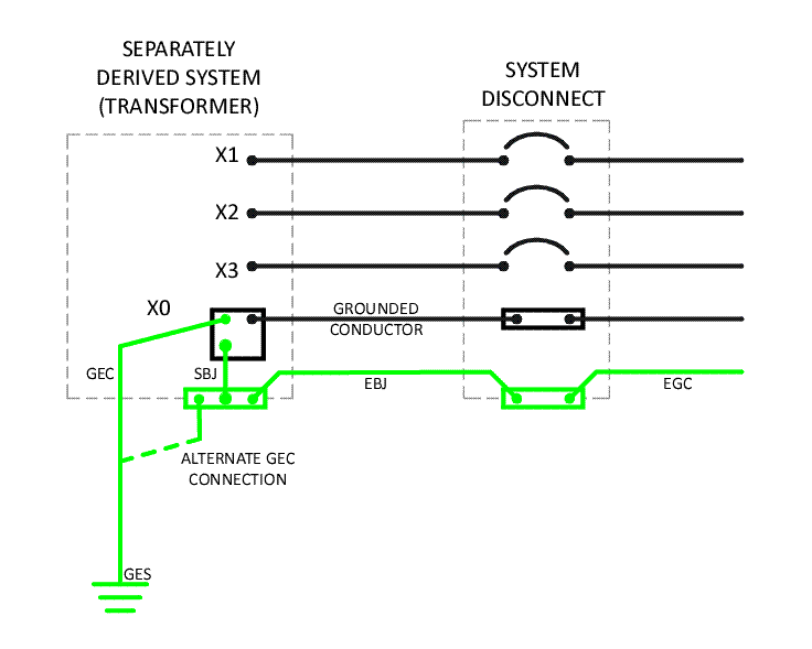
Change that to grounding conductor and you're goodAt this point the ground conductor from the breaker to the lighting panel ground bus is considered an equipment grounding conductor (sized per table 250.122 based upon the secondary breaker rating)?
hurk27
Senior Member
- Location
- Portage, Indiana NEC: 2008
Not sure if you're referring to my choice of terminology "Am currently designing a separately derived system" or something else (like maybe my intelligence). If the terminology above was what you were referring to, it seems appropriate as defined in the code ("Separately Derived System. A premises wiring system whose power is derived from a source of electric energy or equipment other than a service. Such systems have no direct electrical connection, including a solidly connected grounded circuit conductor, to supply conductors originating in another system.")
I miss read you post thinking you were installing a transformer with a 480/208 Y secondary, which is an impossible configuration, but re reading it, I see now, your talking about a 480 volt primary-208/120 secondary.
My mistake.
Last edited:
Sounds good. Here's a diagram (easier than 1000 words
I realize this is fairly picky, but in your diagram shouldn't the word "Source" be inserted after the "Separately Derived System" above the transformer (the transformer is the source of the separately derived system). Thanks again for all the info and insight into likely future code changes.
Yes it is being picky... however it is so noted and will consider improving my rush-a-diagram standards a little higherI realize this is fairly picky, but in your diagram shouldn't the word "Source" be inserted after the "Separately Derived System" above the transformer (the transformer is the source of the separately derived system). Thanks again for all the info and insight into likely future code changes.
- Status
- Not open for further replies.