- Location
- Wisconsin
- Occupation
- PE (Retired) - Power Systems
Then why did you say you needed two phases, when the circuit works because of the two voltages?I couldn't have put it better.
Then why did you say you needed two phases, when the circuit works because of the two voltages?I couldn't have put it better.
But of course. But as I know you know, if either the first subscript or the second subscript of the voltages are not the same, the subtraction result is going to be a voltage larger than either of the two voltages. We both know that we have 240v and 120v voltages, not 360v voltages so to set up a calculation to produce that result is misleading at best.Are you serious?
It is obfuscation to ask that a mathematical equation be able to be solved in other permutations?
Yes, I would expect any student taking a course to be able to solve a single equation for a for a single unknown.
Ah. Two voltages.Then why did you say you needed two phases, when the circuit works because of the two voltages?
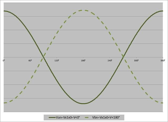
That is the waveform you would have for the voltages I have between the n & b terminals in my circuit.That is not a posting of the waveforms from the circuit where you had {Vbn@180? connected in parallel with Vnb@0?} which was in series with a parallel connection of {Van@0?and Van@0?}.
I am surprised you think it is not representing the voltages in my circuit. Can you please explain how the voltages I have labeled in my circuit are not represented by a graph of two sinusoidals displaced by 180?? I mean, that was the whole point of making my generator example in the first place. If you did not follow it, then I can understand why you failed to get my point.I am surprise you would not have noticed the difference.
But of course. But as I know you know, if either the first subscript or the second subscript of the voltages are not the same, the subtraction result is going to be a voltage larger than either of the two voltages. We both know that we have 240v and 120v voltages, not 360v voltages so to set up a calculation to produce that result is misleading at best.
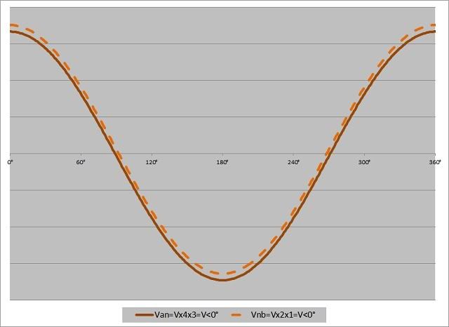
They are in phase. Just like I have repeated in the past.What is the relationship between those two voltages?
No it is not.That is the waveform you would have for the voltages I have between the n & b terminals in my circuit.
I know what I'll do. I will draw my phasors in the same direction.
120Vrms@PI L2---------->N---------->L1 120Vrms@0
Are V1n and V2n in phase? Of the same phase?
Well no. Because the phase angles on L1 and L2 did not change. Whattya know? The voltages are separated in time by half a period--PI radians. One is the inverse of the other.
Then maybe you were not being misleading at all. The math may just be unfamiliar to you and you made an honest mistake.Misleading??
It must have been a tough assignment, I have no idea how you arrived at 360V.
There is nothing wrong with my methodology and my post is correct.If the voltages can be combined to produce a higher voltage, than by the virtue of mathematics then one of them should be able to be subtracted from the higher value without providing a misleading answer.
If you don't like your answer maybe the problem is your methodology and not the question?
That, sir, is some of the worst labeling and notation I have ever seen. How can you possibly expect to do any phasor manipulations for me? I know you own a copy of Blackburn's "Protective Relaying" book. He has a good section on voltage labels and proper use of subscripts. You would do well to review that section.Here let me do the simple phasor manipulation for you.
Van+Vnb=2Vab
2Vab = 240V@0?|-------------------->
Van = 120V@0?|--------->
2Vab-Van =120V@?? this requires the phasors to be connected tail to tail or head to head
So |--------------------> -|---------> = |--------->---------> = --------- I'll let you put in the direction.
Now
Van-Vbn=2Vab
2Vab = 240V@0?|-------------------->
2Van = 120V@0?|--------->
2Vab-Van =120V@?? this requires the phasors to be connected tail to tail or head to head
So |--------------------> -|---------> = |--------->---------> = --------- I'll let you put in the direction.
I suspect they would but I am not even going to attempt to try to interpret the mess you just posted.Do your your phasors differ?
I'll take the high road on that question.Why?
Yes, it is.No it is not.
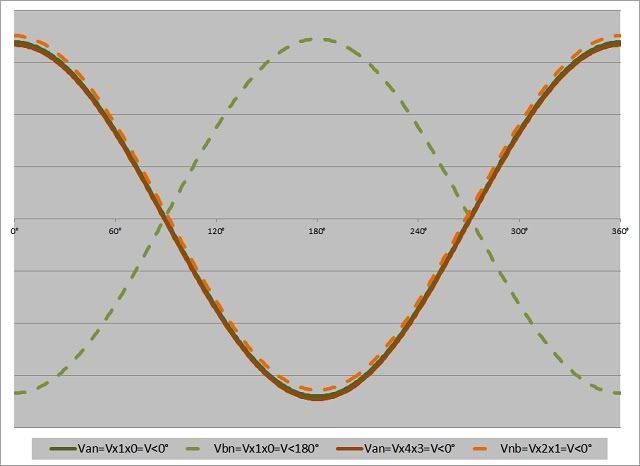
If you do not understand that the Vbn and the Vnb in my example are two sinusoidal waveforms with a 180? displacement, then I really don't know how posting an actual oscilloscope display of Vbn and Vnb that will display two sinusoidal waveforms with a 180? displacement is going to help you.I am waiting for someone to post an actual oscilloscope display of your paralleled Vbn and Vnb in series with your paralleled Van and Van outputs.
Actually, the mistake is in assigning an angle of 180? to this voltage in the first place.Your first exercise was to take 240@0? and subtract 120@180?. How you do not know this yields 360@0? is beyond me.
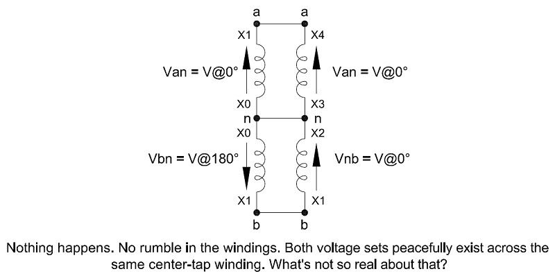
Below are the waveforms for the voltages in my generator example (slightly offset so the plots don't lay right on top of each other).If you do not understand that the Vbn and the Vnb in my example are two sinusoidal waveforms with a 180? displacement, then I really don't know how posting an actual oscilloscope display of Vbn and Vnb that will display two sinusoidal waveforms with a 180? displacement is going to help you.
You set up the exercise so you take ownership of any mistakes you allege are there.Actually, the mistake is in assigning an angle of 180? to this voltage in the first place.
The math does work when you acknowledge the double negative in your methodology.
I do not plan to take any phasor instruction from someone that cannot figure out that a result of 360V must be due to poor direction assignment, and instead blames the math.That, sir, is some of the worst labeling and notation I have ever seen. How can you possibly expect to do any phasor manipulations for me? I know you own a copy of Blackburn's "Protective Relaying" book. He has a good section on voltage labels and proper use of subscripts. You would do well to review that section.
Have you rewired the transformer?
Are you simply redrawing phasor directions while ignoring the subscripts? Because they no longer match.
You have phasors pointed in the same direction but you are saying they have different angles. This is not a proper representation of phasors, so I do not want to guess at what you are attempting to prove.
I'm quite sure your pride won't let you take instruction from me, that is why I suggested you learn from Blackburn. But I'm sure he would also agree that 240@0? - 120@180? = 360@0?I do not plan to take any phasor instruction from someone that cannot figure out that a result of 360V must be due to poor direction assignment, and instead blames the math.
I'm quite sure your pride won't let you take instruction from me, that is why I suggested you learn from Blackburn. But I'm sure he would also agree that 240@0? - 120@180? = 360@0?