Reverse Polarity Bootleg Ground Testing

Status
Not open for further replies.

jxofaltrds

Inspector Mike®
Location
Mike P. Columbus Ohio
Occupation
ESI, PI, RBO
I'm not an engineer but don't you have paralleled conductors here?
Hopefully someone can explain how or if it is possible for the XLR cables to transfer 'noise' via the 'ground'.

Ground%20Loop%20Currents.JPG
 

jmsokol

Member
I'm not an engineer but don't you have paralleled conductors here?
Hopefully someone can explain how or if it is possible for the XLR cables to transfer 'noise' via the 'ground'.

View attachment 7064

Yes, you're absolutely correct. The shield of the XLR (microphone) cable connecting two pieces of AC powered sound gear is in parallel with the outlet safety grounds. Since large sound systems are usually plugged into multiple power outlets due to room size and power requirements, many times this interconnected gear will be on separate branch circuits or even different sub panels. You can just put a clamp-meter right around the signal cable and sometimes measure 3 or 4 amps current flow. I'll show you later just how that ground loop hum sneaks into the amplifier's circuity to make hum. It's a real eye opener.

One cheap/quick trick at live sound gigs that will remove this parallel current path (and hum) is to lift (open up) pin 1 (the shield connection) on one end of the XLR cable, so it acts as a shield but does not offer a parallel current path. However, the ability of the amplifier's input circuitry to cancel this 60 Hz "noise" is based on its CMRR (Common Mode Rejection Ratio) measured in decibels. Active electronics (op-amp) circuits are cheap to build and don't take up much space or weight in a amplifier chassis, which is why they're found in all cheap and many mid-priced amplifiers. They offer reasonable CMRR, but nothing great, especially at RF frequencies when their feedback slew rates run out of gas and do all sorts of mischief.

On the other hand, a properly designed audio transformer from a company like Jensen offers fantastic CMRR (close to 100 dB if memory serves) especially if it has a mu metal shield. And they can sustain hundreds of volts common-mode potential (winding to winding), which an op-amp balanced input has no chance of nulling out. However, good audio transformers are expensive, heavy, and take up a lot of real estate in a chassis. That's why they're only used in expensive sound gear that has to work under all kinds of adverse power and EMI challenges.

You can also add external audio transformers in series with the XLR cables themselves, which is why many soundguys carry a few ISO or Hum Eliminator transofrmers in their tool kits from companies such as Whirlwind or Ebtech. These audio isolation transformers will convert unbalanced signals to balanced, and visa versa, which is also what's needed to stop that power supply "hash/buzzing" noise that can happen when you plug a laptop computer into a mixing console. But that's another posting...
 

Attachments

  • HE2XLR_ezr2.jpg
    HE2XLR_ezr2.jpg
    33.7 KB · Views: 0
Last edited:

rt66electric

Senior Member
Location
Oklahoma
Don't stand on a cord while testing !!!

Don't stand on a cord while testing !!!

If you a standing on a live extension cord, it will affect your Non-contact tester.

I was having trouble troubleshooting. My NCT was reading HOT and my wiggy was reading DEAD. Sometimes it woud beep sometimes not??? While standing on a live cord "you" may be the conductor for the NCT to read a ground path. Similar to a bird on a power line.

I use the Adjustable type NCT tester. A person can ususally adjust the sensitivety to tell the diifense between hot side of cord and neutral/ground side.

Another saftey precaution will working is to leave tester "on" inside your shirt pocket. If you a working on live equipment, your tester will beep when you are "energized and not grounded"
 

jmsokol

Member
NCVT errors

NCVT errors

If you're standing on a live extension cord, it will affect your Non-contact tester. I was having trouble troubleshooting. My NCT was reading HOT and my wiggy was reading DEAD. Sometimes it woud beep, sometimes not??? While standing on a live cord "you" may be the conductor for the NCT to read a ground path. Similar to a bird on a power line.

Yes, you're correct. And if you're standing inside an RV with a hot-skin condition, you can reach out of the door and point your NCVT at the ground and it will beep. I've actually tried this. Fluke claims that if you're standing on a fiberglass ladder that your body will be too far from the earth to establish a ground plane, but I've been on some tall fiberglass ladders and never saw this effect. Has anybody seen that happen on a tall ladder?

I use the Adjustable type NCVT. A person can ususally adjust the sensitivety to tell the diifense between hot side of cord and neutral/ground side.
That works for somebody in the electrical trades who understands the idea of calibration, but I don't like it for consumers who will mess around with the sensitivity slider until it reads what they like. So they need a non adjustable unit.

Another saftey precaution will working is to leave tester "on" inside your shirt pocket. If you a working on live equipment, your tester will beep when you are "energized and not grounded"

A buddy of mine who's a POCO lineman does just that. He always turns on his NCVT while walking in the woods looking for downed and possibly energized power lines. He says his Fluke starts beeping quite a distance from a downed 11KV line laying on the ground.
 

hurk27

Senior Member
A buddy of mine who's a POCO lineman does just that. He always turns on his NCVT while walking in the woods looking for downed and possibly energized power lines. He says his Fluke starts beeping quite a distance from a downed 11KV line laying on the ground.

That reminds me of a time about 15 years ago, I had a greenlee adjustable one that was very sensitive enough you could use it as a poor mans wire tracer turned all the way up using the power to follow the wires, well in this one neighborhood I had a house ware the drywallers buried several box's and I was sent out to find them, well I got out the greenlee and turned it on, immediately it went nuts even at the lowest setting waved it around didn't matter it was going nuts, normally at the lowest setting you have to be touching the wire to make it beep, well thought maybe bad batteries? went out to the van installed a new set turned it on it went nuts again, I'm like whats going on??? I not even near the house and all the utilities are in the ground, again I started pointing it around and just as I started moving up it smacked me right in the face:slaphead:, right above where I was standing was a 500kv lines about 200' up above me that went right over this neighborhood, :ashamed1: to this day I still do not know why they let that contractor build right under those lines but they did.
 

jmsokol

Member
NCVT on a stick

NCVT on a stick

Here's a pic of the Extech DV-50 NCVT, which has a telescoping, non-conductive fishing pole with the tester gadget out on the end. It reaches out something like 39" from the handle so you can walk around and use it to test for "hot" manhole covers on the street. It would also work to check metal light poles for "hot" problems. It's pretty loud and has adjustable sensitivity, and really squawks and flashes when it finds anything energized.

Extech sent me one last week to try out, and the only thing I don't like is that it uses little "watch" batteries rather than AAA batts. But that's not really too big a deal as long as you keep some spares in your toolbox. It's a little beefier than I imagined, so you might need to switch hands every so often since all the weight is cantilevered out on a pole. But it appears to be just the thing for doing a city-wide check of manhole covers and light poles for voltage/shock issues.
 

Attachments

  • dv50.jpg
    dv50.jpg
    27.4 KB · Views: 0

hurk27

Senior Member
I want to point out to make the understandable point of how a ground loop works there are two problems with your diagram, Don't get me wrong I think its a great design for those who are in the sound end of things, but it really doesn't show how the current gets onto the green GEC at the bottom, but a couple changes would make it much more clearly: at the receptacle on the left or in the cord show a neutral to ground fault, at the receptacle on the right complete the path to the main breaker panel showing the main bonding jumper between the neutral, this would make a clear example of how current can be put on a EGC when it is now in parallel with the neutral, without this neutral to EGC fault there would be now parallel path and the EGC wouldn't have current on it, of course there are other reasons for current on the EGC and some even in a NEC code compliant install, one such problem comes up where equipment is powered from outlets fed from two different services or transformers, this can happen in very large venues that might have multiple SDS's all over the place feeding local 120/208 loads, the only code compliant method of fix in this case would be the hum buster box in your post above or what I kept around was Switch Craft matching transformers.

Another cause is of course the old stage hand or more better known as the bands roadie who also takes care of their equipment miss wires a cord end switching the neutral and ground "well it works it must be right" and now you have a take every where hum, no matter where they go:lol:

attachment.php
 
Last edited:

jmsokol

Member
FIx the Pic

FIx the Pic

I want to point out to make the understandable point of how a ground loop works there are two problem with your diagram... but it really doesn't show how the current gets onto the green GEC at the bottom....

attachment.php

Yes I know it's not very clear on a schematic level. I use this in my NoShockZone PPT presentation for sound installers showing them where to place a clamp meter to find ground loop currents. I have another slide which shows the current path in XLR cables connected to a double-bonded G-N in a subpanel. I'll draw up a more complete version over the weekend and submit it for all or you to review for accuracy.

I'll still use this simple slide for my basic NSZ class, but it will be good to get the entire ground loop wiring path on a single slide for those who can actually read a schematic.

Ref your comment about ground loop hums in really large gigs from multiple SDS's all over the place: I always put an audio isolation transformer on the mixing console's matrix output feeding the video truck. They do some pretty strange things in video land such as driving their own ground rods, running from a genny and who know's what else. I don't want their ground contaminating my ground and starting a hum a I can't fix in the middle of the broadcast.

You know that the sound-guy ALWAYS gets blamed for anything that goes wrong on a gig....:lol:
 

K8MHZ

Senior Member
Location
Michigan. It's a beautiful peninsula, I've looked
Occupation
Electrician
Here is what Ideal instructions say.

Note:​


1. All appliances or equipment on the circuit being tested should be unplugged tohelp avoid erroneous readings.2. Not a comprehensive diagnostic instrument but a simple instrument to detectnearly all common improper wiring conditions.3. Refer all indicated problems to a qualified electrician.4. Will not indicate quality of ground.5. Will not detect two hot wires in a circuit.6. Will not detect a combination of defects.​


7. Will not detect reversal of grounded and grounding conductors.


So who is asking these juvenile questions, pros, amateurs or both?

Just curious.

Roger


It doesn't say anything about the issue with the hot and neutral reversed does it? That's not the same as the grounded and grounding conductors being reversed.
 

jmsokol

Member
It doesn't say anything about the issue with the hot and neutral reversed does it? That's not the same as the grounded and grounding conductors being reversed.

Here's a story from one of the professors I work with at the Conservatory. Adam teaches recording studio maintenance (among other things) so he knows his way around a DMM and can read schematics. When he wanted to rewire the room in his 100 year old house, he tried to do the right thing and hired a licensed electrician, but obviously the electrician knew a lot less about RPBG's than he should. Here is Adam's story, which I'm using in an upcoming article I'm writing about hot ground dangers.

Take it away, Adam...

My wife and I, and our son moved to a house five minutes from downtown Denver. We turned the entire upstairs into a recording studio. The house being over 100 years old, when it was wired for electricity, it had several 2 prong outlets. I was planning on rewiring the outlets myself but we felt it was best to have a licensed electrician with insurance do the wiring. The electrician came in and rewired the house/studio, stating that he didn?t really enjoy working on resident jobs because they weren?t as challenging as big commercial jobs. Little did he know at the time the challenge being presented him.

Unfortunately, the outlet was already wired incorrectly previously, with hot and neutral reversed, and the wire coloring also backwards! After he tied ground to neutral on the new 3-prong outlet my new found studio was ready for connectivity. I thanked him for his work and over the course of the next month or so a series of strange events occurred.

The first event happened after we purchased a new HP refurbished printer for a couple hundred dollars. The printer was placed in the kitchen and used the same outlet the refrigerator. I connected a long USB cable from the studio computer to the printer. When I made the connection I saw and heard colorful sparks come off the USB cable and printer. I returned the printer back to the store thinking to myself it must be the new ?refurbished? printer that was the problem since my studio had been running fine for at least a week now.

A few weeks later incident number two happened. My fairly new Digi 002R which had been working fine for a while had a Firewire port die after connecting it to my Mac laptop (no sparks this time). Doing some research I found that they have been known to have some Firewire issues, so I had it fixed by Digidesign. Weeks passed and other similar mysterious events happened, but nothing as incredible as the refurbished printer sparks, probably due to small wires in enclosures as Mike has previously mentioned. The final kicker that sent me into full-scale investigation happened when I connected audio from my AC powered Mac laptop, which was connected to a properly wired outlet. I patched a ?Y? cable into the patchbay connected to the mixer, and then into my headphone out on my laptop, again sparks flew and factory installed smoke gushed from my laptop!

I used my multi-meter on each of the outlets and they tested as expected. Clearly there was an issue between the outlets, so I ran an extension chord and checked what happened between the outlets and? ?what was this?!? 120 volts between my grounds! Flabbergasted I went and purchased a 3-light tester and read the packaging carefully, I found that indeed it stated that it wouldn?t indicate both a hot neutral and hot ground.

I called my father (Bruce Olson) a licensed appliance repairman. He guided me through documentation and proper steps for reimbursement for damage. As expected the electrician denied that it could have been anything he did and that he tested the outlet properly. After he saw the tests I ran, and the packaging that 3-light testers don?t work for this issue, I asked him if he would rewire and reimburse us for the damage. His first response was that he wasn?t going to do anymore wiring in this place at all.

He went outside and called his boss, about 20 minutes later he came back and ran a dedicated 20-ampere outlet directly to the breaker box, drilling a hole through the wall and brick to boot! After much paper work and time all reimbursements were made and Studio Prime was back up and running!

END

Hey, I'm back. Thanks Adam....

So you see that even though many or even most of you on this forum may understand the limitations of 3-light outlet testers, there are a lot of electricians and inspectors out there who obviously don't have a clue. A customer should NEVER have to diagnose an electrician's mistake! I first discovered "cube" tester limitations more than 25 years ago when I was working on a rental property for my dad, and found a few outlets that were wired "backwards" with hot grounds right after the inspection passed them all. Funny thing is, the county rental inspector said that as long as her 3-light tester showed two yellow lights and no red light, she would pass the electrical in the rental property.
 

roger

Moderator
Staff member
Location
Fl
Occupation
Retired Electrician
It doesn't say anything about the issue with the hot and neutral reversed does it?
I think #6 basically covers that as well as many other possible problems don't you?

Roger
 
Last edited:

roger

Moderator
Staff member
Location
Fl
Occupation
Retired Electrician
So you see that even though many or even most of you on this forum may understand the limitations of 3-light outlet testers, there are a lot of electricians and inspectors out there who obviously don't have a clue.
Very true , the same applies to General Contractors, Mechanics, Plumbers, Pilots, etc..., [/quote]
A customer should NEVER have to diagnose an electrician's mistake!
True again, but the customer should do a better job trying to find a reputable contractor.
I first discovered "cube" tester limitations more than 25 years ago when I was working on a rental property for my dad, and found a few outlets that were wired "backwards" with hot grounds right after the inspection passed them all. Funny thing is, the county rental inspector said that as long as her 3-light tester showed two yellow lights and no red light, she would pass the electrical in the rental property.
That is sad but, it will not change anything as far as DIYers and Unqualified people using tools they don't know how to use be it electrical, automotive, neuro surgery, or what have you.


Roger
 

K8MHZ

Senior Member
Location
Michigan. It's a beautiful peninsula, I've looked
Occupation
Electrician
I think #6 basically covers that as well as many other possible problems don't you?

Roger

Not detecting something and indicating that it is correct are two different things.

My problem is that the labeling on the tester indicates 'correct' when it should say 'no error detected'. I see nothing that clues in the user that 'correct' means anything but exactly that. Sure, the instructions mention that multiple errors can't be detected, but don't mention that 'correct' doesn't really mean correct.
 

rt66electric

Senior Member
Location
Oklahoma
Would a surge protector prevent stage equipment damage?

Would a surge protector prevent stage equipment damage?

In response to the $8000 damage to the audio gear.... would have installing one of those $100 surge plug strips prevented damage?? This Is a great thread!!!
 

don_resqcapt19

Moderator
Staff member
Location
Illinois
Occupation
retired electrician
Not detecting something and indicating that it is correct are two different things.

My problem is that the labeling on the tester indicates 'correct' when it should say 'no error detected'. I see nothing that clues in the user that 'correct' means anything but exactly that. Sure, the instructions mention that multiple errors can't be detected, but don't mention that 'correct' doesn't really mean correct.
For the average user, I don't think they would do anything differently if the label was changed from "correct" to "on error detected". To most those terms will mean the same thing.
 

jmsokol

Member
In response to the $8000 damage to the audio gear.... would have installing one of those $100 surge plug strips prevented damage?? This Is a great thread!!!

Sadly no...

A typical surge protector works by monitoring the H to N and H to G voltages with a pair of little MOV semi-conductors that sort of look like red nickles. If there's a potential over about 200 volts peak, the MOV devices will short for a brief instant. (remember 120 volts RMS [Root Mean Square] times the square root of 2 ( which is 1.414) comes out to 170 volts peak). So if there's a voltage spike on the power line from a nearby lightning strike or power-line snafu (commonly called a surge) then the MOV device will short it out and trip the circuit breaker. And sometimes they just die trying.

However, a surge strip is really no smarter than your DMM when measuring outlet voltage since it has no reference to actual earth ground. So plugged into a RPBG outlet it will assume everything is perfectly fine since it's still only measuring H to N and H to G potential. And while there are advanced surge protectors for big RV's shore power connection (see my NSZ article at http://www.noshockzone.org/rv-electrical-safety-surge-strips/ ) they still can't detect a RPBG wired by a campground electrical guy (I won't call him and electrician) causing a hot ground on the campsite pedestal. However, while these $300 surge/monitor boxes will check the line for high and low voltages, they only disconnect the H and N buses via a relay. That still leave the safety ground connected on the RV chassis while they're tripped, so there's always the possibility of the fancy RV surge protector shutting off the H-N connections, but leaving the hot-Ground contact in the outlet still tied to the chassis of the RV. I've tried this out myself and measured the effect, and then talked to the RV surge box manufacturers to confirm that's how their products work. They seemed a little embarrassed when I called them out on that safety issue, but I've not seen any product fixes.

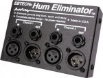
I've also done sound on a number of stages where the guitar players cut off the ground pins on their amplifier power cords, then tell me not to worry because they have a very expensive "surge strip" that will protect them from getting shocked. Again, that's also a bunch of misinformation since a surge strip is there to protect the gear, not the consumer.

The other interesting fact is that many surge strips introduce up to 3 to 4 ma leakage between the H and G buses. That's not enough to trip the GFCI by itself, but if you plug TWO surge strips together on the same GFCI outlet, it will usually exceed the 5 to 6 ma threshold and trip the GFCI breaker. I think that's why so many music clubs illegally remove the GFCI outlets on the stage. Too many "random" GFCI trips that shuts down the band will NOT be tolerated. You may also seen random tripping of GFCI's on A-V media systems which many times will have more than one surge strip plugged into a single GFCI outlet.

I've been studying this for a while and don't have all the answers yet, but I'm working on it. If there are any GFCI or surge protector engineers on this forum, I would love to hear their take on it.
 

kwired

Electron manager
Location
NE Nebraska
In response to the $8000 damage to the audio gear.... would have installing one of those $100 surge plug strips prevented damage?? This Is a great thread!!!

No. If voltage between the conductors is below clamping voltage it does nothing, and it doesn't care about polarity, maybe a higher priced one will indicate wiring errors but like the plug in tester, if neutral and ground are near same potential it doesn't know whether they are grounded or not just that they are about same potential.
 

jmsokol

Member
Beam me up, Scotty

Beam me up, Scotty

For the average user, I don't think they would do anything differently if the label was changed from "correct" to "on error detected". To most those terms will mean the same thing.

It's amazing to me just how little the average DIY'er knows about electricity. And yet they can buy pretty much any electrical supplies and meters they want at most any big box store. The problem is that whatever warning text you put on the label they will only read it as "blah, blah, blah".

I had a student at one of my remote NoShockZone seminars accuse me of making all the words up. I was using terms like Volts and Amps and Current Flow. At the end of my 90 minute seminar she came up to me and said it all sounded like Greek to her and how did she know that any of what I was saying was true. Sort of like I was sprinkling fairy dust in the room and telling them they could all fly. The home room instructor, who happens to be a ham radio operator, told her I was definitely NOT making any of this stuff up. That I was simply repeating and demonstrating the most basic principals of electricity as discovered and quantified by Voltaire, Ampere, and others from hundreds of years ago. She didn't believe him either.

Oh, she was in a technical class learning how to record and edit television audio for broadcast. Good luck with her understanding decibels and impedance. I'll bet she doesn't read warnings on gear labels either... or bother to test ANYTHING!!!!
 

don_resqcapt19

Moderator
Staff member
Location
Illinois
Occupation
retired electrician
... The problem is that whatever warning text you put on the label they will only read it as "blah, blah, blah". ...
Part of that is because there are warning labels on almost everything and no one really reads any of them any more.
 

jmsokol

Member
Volta vs Voltaire

Volta vs Voltaire

The home room instructor, who happens to be a ham radio operator, told her I was definitely NOT making any of this stuff up. That I was simply repeating and demonstrating the most basic principals of electricity as discovered and quantified by Voltaire, Ampere, and others from hundreds of years ago. She didn't believe him either.

Oops... In the interest of accuracy, I accidentally wrote that Voltaire was the guy who we named Volts after, when in fact it was Volta, as in Count Alessandro Giuseppe Antonio Anastasio Volta (February 18, 1745 ? March 5, 1827) :eek:hmy:

Voltaire was a French philosopher about the same time, but definitely NOT involved in electricity experiments. Good thing I didn't say that in front of a class as my students double check me with their smart phones all the time.... as do my own kids. Helps keep me accurate.

Yeah, it's not all that important, but I really don't like inaccuracies on the Internet. Flog me with 48-channel snake fanout. :lol:
 
Status
Not open for further replies.
Top