Current transformers in a panelboard

Status
Not open for further replies.
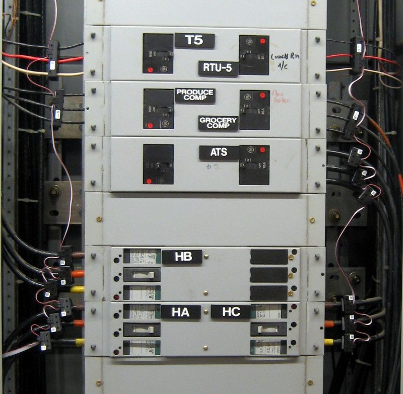
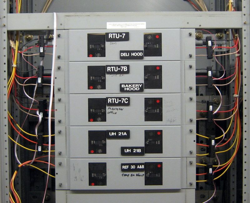
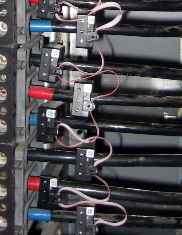
Was out at a job today to help a buddy with a geothermal heat pump install (needed a 60amp circuit for backup heat) and saw something that I haven't seen in a residential setting before. The homeowner is an engineering type and has installed a power monitoring and managing system. The CTs are installed before the main but inside the panelboard, not in another box. They are wired to the monitoring device along with a voltage signal from a 15amp 2 pole breaker.

Is this legal under NEC 08? (NEC 11 has not been adopted here yet)
 

gar

Senior Member
Location
Ann Arbor, Michigan
Occupation
EE
120728-1918 EDT

Your description could be of a TED system.

Why do you think it is a problem?

If it is a TED system, then what I don't like is the extreme thin insulation on the wires to the current transformers. These are not mechanically rugged, could be cut thru easily.

Also functionally the TED system has problems with non-unity power factor. It can not be used to prove that a power factor correction capacitor installed at a residential main panel is of no value. Also has substantial problems with PLC (power line carrier communication), and in the newer system a lot of software problems.

.
 
120728-1918 EDT

Your description could be of a TED system.

Why do you think it is a problem?

.

Its not that I think its a problem, Im only curious.

Its not a TED system. The guy has ammeters on the panel to see current rate of consumption. (The guy said he has teenagers and likes to see how much power all there electronic devices use)

The wiring is THHN 12 ga for the CTs and the voltage sample.
 

gar

Senior Member
Location
Ann Arbor, Michigan
Occupation
EE
120728-2232 EDT

iwire:

The TED system is a whole house power, voltage, and energy monitoring system. TED is derived from The Energy Detective. The older system was identified as 1000 and the new one 5000. The 1000 system did not provide VA output or PF and thus PF was not available. The 5000 system includes VA and from this PF is calculated.

There are both quality and bug problems in both systems. If you understand the structure of the systems a number of the problems or issues can be solved or avoided.

I have made effective use of the 1000 system. You can see some of my results at http://www.beta-a2.com/energy.html . The data for the plots came from my home and sampled at the rate of once per second. Even though the plot 9.8.2.2 encompasses 24 hours it still shows 1 second results. The spikes are motor startup power. These are mostly freezers, refrigerator, and furnace blower.

Last week, while we still had power problems, I used TED to monitor the voltage at my son's shop. There apparently was about 3 addition miles of cable added to the primary of one of our phases to get power from a different substation. With hot weather last week one saw a smooth variation of voltage on the bad phase from a high of about 116 V around 4 in the morning to a low about 105 V in the middle of the afternoon. No particular spike variations other than internally generated by our big laser printer.

.
 

templdl

Senior Member
Location
Wisconsin
I would be curious what type of CTs he used. Are they the window CTs that you can open and close around the wire of did the power need to be disconnect and the wire put through the CTs?
Either way as I understand it the homeowner owns the conduit and cable from the POCO meter to the panel anyway. But the meter may have had to be pulled to install the CTs.
Just a thought.

They are standard toroid (donut) type CTs. Either he had the meter pulled or they were installed very carefully :rant: so not to arc.

Here is a pic. The top of the panel is very crowded. I added the circuit to the sub-panel that was for HVAC (100a feeder), not the main panel.

http://i.imgur.com/o4CmZ.jpg

S
ide question: When sharing pics, is it ok to use sites like imgur? I saw someone else using it and I find it simpler to give a simple link as opposed to uploading it to the forum.
 

iwire

Moderator
Staff member
Location
Massachusetts
o4CmZ.jpg


I don't see any issue in your pic other than the heavy use of tape. :)

Feel free to use any image host you want. :)


Here is an installation I did about a month ago

IMG_1007.jpg


IMG_1005.jpg


IMG_1009.jpg
 

gar

Senior Member
Location
Ann Arbor, Michigan
Occupation
EE
120729-1340 EDT

steve:

Are there two voltmeters or just one. If a single voltmeter, then does it measure leg to leg or just one leg to neutral?

Are there two ammeters or just one?

Is there other circuitry to measure power? Because power at a home is not simply V*A. Any recording equipment?

Are the meters RMS reading?

By any chance did this customer also install a whole house power factor correction capacitor?

Can this customer actually reduce his electric bill as a result of having installed this instrumentation? How often does he run to the main panel to read the meters? What did these meters, and associated equipment cost?

.
 

templdl

Senior Member
Location
Wisconsin
iwire, you had the benefit of being able to disconnect the power before inserting the wire threw the censors but it would be interesting to know how the homeowner if stevephillips' example accomplished what he did. Either he was very gutsy or he had the meter pulled first.
 

hillbilly1

Senior Member
Location
North Georgia mountains
Occupation
Owner/electrical contractor
o4CmZ.jpg


I don't see any issue in your pic other than the heavy use of tape. :)

Feel free to use any image host you want. :)


Here is an installation I did about a month ago

IMG_1007.jpg


IMG_1005.jpg


IMG_1009.jpg
Three window ct's? That's kinda unusual. Some of the systems we put in just uses one phase to calculate the load if it is a straight three phase load such as an RTU, we just have to pick one of the two legs that the unit manufacture uses for the single phase condenser fans.
 

iwire

Moderator
Staff member
Location
Massachusetts
Three window ct's? That's kinda unusual. Some of the systems we put in just uses one phase to calculate the load if it is a straight three phase load such as an RTU, we just have to pick one of the two legs that the unit manufacture uses for the single phase condenser fans.

If this was a standard size 42 circuit panel you would see seven of the three window CTs down each side. Each window is it's own address so a three window CT could handle 3 single poles, or single and a two pole etc.

Each pole also uses a set screw to pierce the insulation and monitor voltage right at the CT.
 

hillbilly1

Senior Member
Location
North Georgia mountains
Occupation
Owner/electrical contractor
If this was a standard size 42 circuit panel you would see seven of the three window CTs down each side. Each window is it's own address so a three window CT could handle 3 single poles, or single and a two pole etc.

Each pole also uses a set screw to pierce the insulation and monitor voltage right at the CT.

Interesting, I have not used any of those type before. We use a lot of Veris split cores, with a small amount of rope ct's, the EMS companies don't like the rope ct's though because they don't give all the circuit info they want.
 
iwire, nice work.

I guess that answers my question as to if its allowed by code to put CTs in a panelboard. Last question, does the secondary of the CT need to be grounded? In this case, it wasn't.
 
Status
Not open for further replies.
Top