Question about calculating voltage drop on 3 phase inductive circuits

Status
Not open for further replies.

Smart $

Esteemed Member
Location
Ohio
Will you accept a limiting case and agree that the real world will lie somewhere between the extremes?

Try this on for size: Load has a PF of 0 with XI=6 ohms. W(ith a 120 volt VS, the current is 20 Amps.
Assume wiring with R=2 ohms and XL=0.
(Unperturbed voltage drop across the wires would be 40 volts. Actual voltage drop will be less, since the current will go down, but not by much, so let's do the numbers.)
Overall impedance is 6 + 2j.
"6 + 2j"...???

I know it still amounts to 6.32 ohms, but isn't Z = R + jX, therefore 2 + j6?

The current will now be 120/6.32, which is 19 amps. The voltage across the load will be 19 x 6 = 114 volts. The drop in voltage seen by the load is 6 volts, so Zeff would be .32 ohms while R=2 ohms. (The drop across the wiring is 38 volts.)
While its an "effective" example [pun intended], it don't fit the effective impedance definition in the NEC.

Ze = R ? PF + XL sin[arccos(PF)]

Ze = 2 ? 0 + 0 sin[arccos(0)] = 0


If the load had a PF of 1, the vectors would all line up and the series resistance would be 8 ohms, current would be 15 ohms [amps], voltage across the load would be 90 volts and voltage across wiring would be 30 volts, so Zeff would be 30/15 = 2 ohms = R.
Spot on. At least we have a winner for IR = IZ :happyyes:

If you put in more realistic numbers, and use a reasonable PF, the vector directions get messier and the math gets harder to do, but the result will still be, for some wire impedances, that Zeff < R.
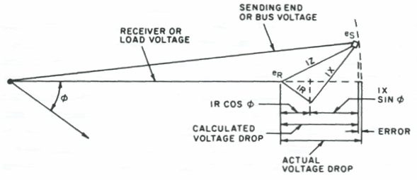
FWIW, here's the diagram associated with the approximate IEEE method:

V-drop_diagram.gif
 

GoldDigger

Moderator
Staff member
Location
Placerville, CA, USA
Occupation
Retired PV System Designer
"6 + 2j"...???

I know it still amounts to 6.32 ohms, but isn't Z = R + jX, therefore 2 + j6?

Details, details...
Thanks for the catch. :)

And, yes the definition of Zeffective may not match what the Effective Z is, sigh. Electrons are so much more predictable than words.
And, of course, the example drawing uses an angle, phi, that you cannot determine in advance since it is based on the Receiver voltage rather than the Source voltage.
 
Last edited:

Smart $

Esteemed Member
Location
Ohio
Electrons are so much more predictable than words.
:slaphead:

And, of course, the example drawing uses an angle, phi, that you cannot determine in advance since it is based on the Receiver voltage rather than the Source voltage.
As I understand it, phi (ϕ) is the angle establshed by the circuit power factor (cos ϕ).

Mivey used theta (Θ) in his calculations.
 

GoldDigger

Moderator
Staff member
Location
Placerville, CA, USA
Occupation
Retired PV System Designer
As I understand it, phi (ϕ) is the angle establshed by the circuit power factor (cos ϕ).
Well, let me return the favor. :)
The angle ϕ is the load power factor (a constant of the load, or anyway a function of the load and its running condition), not the circuit power factor which will depend on the wiring impedance too.
 

Smart $

Esteemed Member
Location
Ohio
Well, let me return the favor. :)
The angle ϕ is the load power factor (a constant of the load, or anyway a function of the load and its running condition), not the circuit power factor which will depend on the wiring impedance too.
Correct are you :p

Believe it or not, I threw that out there to see if anyone would catch it!!!
 

mivey

Senior Member
Again no indication of vector values.
The voltage drop IZ is the voltage difference between the source and load voltage vectors, specifically stated or not.

I think it's more that Haji, prior to post #30, stimulated a vector anlysis and it carried over into your replies to Bes'.
Could be.

Now can we get back on track? The objective was and remains to show an instance of IR > IZEFF, where IZEFF = VD = |VS| - |VR|.
The objective from #30 was to show IR exceeding IZ. That is never going to happen so we have to leave the track.

But if you want R>Zeff then depending on whether or not Zeff is approximate or exact:
Post #20: 44 instances
Post #22: 44 instances
Post #32: 6.0 > 5.2 so IR > IZeff
Post #40: 14.9976 * 0.4001 = 6.0005 > 5.2226 so IR > IZeff(exact)
Post #42: 6.002 > 5.2234 so IR > IZeff(exact)
Post #42: 6.002 > 5.1853 so IR > IZeff(approx)
Post #45: 10 > 8.55 so IR > IZeff(exact)
Post #48: 84.8528 > 35.1472 so IR > IZeff(exact)
Post #52: 84.8528 > 35.1472 so IR > IZeff(exact)

I guess I should have connected the dots but I just thought the point was obvious. Sorry if it was not.
 

mivey

Senior Member
While its an "effective" example [pun intended], it don't fit the effective impedance definition in the NEC.
The canonic definition of Zeff is ( |Vsource| - |Vload| ) / |I|. The fact that the NEC version is an approximation of Zeff does not negate the exact Zeff.
 

Haji

Banned
Location
India
The relationship is that they are based on the same two voltage vectors (V_source and V_load). However, they are two different calculations using those two vectors.
The relationship is the absolute value of vectors V_source and V_load is either equal to or greater than the magnitude differences between the two. The possibility of equality shows that they are not different things.
The approximate is ok when there is a small angle between the voltage vectors.
If magnitude difference of voltages is approximately equal to I*Zeff which is in turn approximately equal to the absolute value of I*Z for small angles between the voltage vectors, then magnitude difference of voltages is approximately equal to absolute value of I*Z for small angles between the voltage vectors.

Θ
= 0? (the load is resistive).

Vdrop approximate = I*(RcosΘ+XsinΘ) = 84.8528*(0*1 + 1*0) = 0 volts. The approximation is not so good so we should use the exact solution which gives us 35.1472 volts. The voltage impressed on the feeder is 84.8528 volts and is not the voltage drop we seek.

But how can you use load power factor angle for the angle between feeder circuit voltage drop and current through it?
 
Last edited:

mivey

Senior Member
The relationship is the absolute value of vectors V_source and V_load is either equal to or greater than the magnitude differences between the two. The possibility of equality shows that they are not different things.
|Vs - Vr| and |Vs|-|Vr| are quite obviously two different things. If you can't see that then I really don't know what to say.

If magnitude difference of voltages is approximately equal to I*Zeff which is in turn approximately equal to the absolute value of I*Z for small angles between the voltage vectors, then magnitude difference of voltages is approximately equal to absolute value of I*Z for small angles between the voltage vectors.
They are not the same thing. Calculating the exact values for both will show you that. Just because two values round to an equal number do not mean they represent the same thing.

But how can you use load power factor angle for the angle between feeder circuit voltage drop and current through it?
You can't. The load power factor angle and the feeder power factor angle can be different. The load power factor angle is used because it was how the exact equation was derived. The R & X of the feeder take care of the feeder.
 

Haji

Banned
Location
India
|Vs - Vr| and |Vs|-|Vr| are quite obviously two different things. If you can't see that then I really don't know what to say.
You are correct. I agree with you. What more you expect from me? :)
They are not the same thing. Calculating the exact values for both will show you that. Just because two values round to an equal number do not mean they represent the same thing.

Already agreed. My point is any one: absolute value of vector (Vs-Vr), the absolute of I*Z, or the magnitude difference of vectors Vs and Vr may be used to calculate approximately feeder voltage drop, as they are approximately equal to one another for small vector angles as you already stated.
I hope you agree with that.
You can't. The load power factor angle and the feeder power factor angle can be different. The load power factor angle is used because it was how the exact equation was derived. The R & X of the feeder take care of the feeder.
So the exact equation for Zeff [=(RcosΘ + XsinΘ)] can not be used for calculation of feeder voltage drops in all cases for which Vdrop=I*Z, where Z=actual impedance of feeder circuit, should be used.
 

Smart $

Esteemed Member
Location
Ohio
The voltage drop IZ is the voltage difference between the source and load voltage vectors, specifically stated or not.
And my point has been: perhaps for you, but not for everyone. Some of us take it in the context of discussion to mean |I||ZEFF|.
 

Smart $

Esteemed Member
Location
Ohio
The canonic definition of Zeff is ( |Vsource| - |Vload| ) / |I|. The fact that the NEC version is an approximation of Zeff does not negate the exact Zeff.
True. I did say it was an "effective" example. :happyyes:

IIRC, I did not state anything to the contrary.
 

mivey

Senior Member
My point is any one: absolute value of vector (Vs-Vr), the absolute of I*Z, or the magnitude difference of vectors Vs and Vr may be used to calculate approximately feeder voltage drop, as they are approximately equal to one another for small vector angles as you already stated.
I hope you agree with that.
Yes.

So the exact equation for Zeff [=(RcosΘ + XsinΘ)]
The general impedance relationship is Z = V/I. Since it uses that same type relationship (a voltage divided by a current), the exact Zeff = Vdrop/I. RcosΘ + XsinΘ is an approximation for Zeff.

can not be used for calculation of feeder voltage drops in all cases
As an approximation, it does have its limitations.
 

mivey

Senior Member
And my point has been: perhaps for you, but not for everyone. Some of us take it in the context of discussion to mean |I||ZEFF|.
I know that is your focus, and the focus of the original query. When someone states that Z can't be less than R, they are obviously referring to the IZ shown in the IEEE diagram.

In post #4 you were talking about R & Zeff.

In post $7, Besoeker was talking with wes about R & Z as it is used in calculating the voltage across the feeder impedance, which is also called a voltage drop but not the one we are referring to (the load and source magnitude difference).

IMO, you are the one that got the whole thing sideways in your post #11 when you started comparing your R & Zeff values with Besoeker's R & Z values without explaining that you were talking about something different.

I tried to explain in #14 and #17 that you & he were talking about two different things but I guess a track once jumped...
 

GoldDigger

Moderator
Staff member
Location
Placerville, CA, USA
Occupation
Retired PV System Designer
And my point has been: perhaps for you, but not for everyone. Some of us take it in the context of discussion to mean |I||ZEFF|.

Injecting some real world anchor points back into the discussion, what the load cares about (and often that is the reason for limiting the Voltage Drop) is the magnitude of the voltage waveform it sees. It could care less about the phase relationship between that and the source voltage waveform!
For that reason, the VD which is defined as (|Vs| - |Vr|) is the number you need to know to derive |Vr| from knowing|Vs|. In that same situation, knowing |Vs - Vr|, or even knowing (Vs - Vr) is not as relevant.
 
Status
Not open for further replies.
Top