"6 + 2j"...???Will you accept a limiting case and agree that the real world will lie somewhere between the extremes?
Try this on for size: Load has a PF of 0 with XI=6 ohms. W(ith a 120 volt VS, the current is 20 Amps.
Assume wiring with R=2 ohms and XL=0.
(Unperturbed voltage drop across the wires would be 40 volts. Actual voltage drop will be less, since the current will go down, but not by much, so let's do the numbers.)
Overall impedance is 6 + 2j.
I know it still amounts to 6.32 ohms, but isn't Z = R + jX, therefore 2 + j6?
While its an "effective" example [pun intended], it don't fit the effective impedance definition in the NEC.The current will now be 120/6.32, which is 19 amps. The voltage across the load will be 19 x 6 = 114 volts. The drop in voltage seen by the load is 6 volts, so Zeff would be .32 ohms while R=2 ohms. (The drop across the wiring is 38 volts.)
Ze = R ? PF + XL sin[arccos(PF)]
Ze = 2 ? 0 + 0 sin[arccos(0)] = 0
Spot on. At least we have a winner for IR = IZ :happyyes:If the load had a PF of 1, the vectors would all line up and the series resistance would be 8 ohms, current would be 15 ohms [amps], voltage across the load would be 90 volts and voltage across wiring would be 30 volts, so Zeff would be 30/15 = 2 ohms = R.
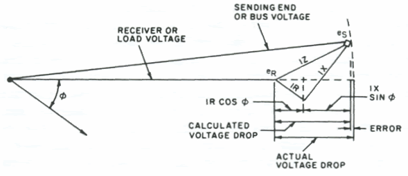
FWIW, here's the diagram associated with the approximate IEEE method:If you put in more realistic numbers, and use a reasonable PF, the vector directions get messier and the math gets harder to do, but the result will still be, for some wire impedances, that Zeff < R.

