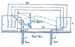
Both Rart and Raux are resistances measured to remote earth. A ground fault current flowing through Rart should also flow through Raux to return to source via the grounded neutral. If Vt1 is the touch voltage at source side and Vt2, on the load side, V0 is the voltage drop along the neutral wire and Isc is the ground fault current, then
V0=Vt1+Vt2=(Isc*Rart)+(Isc*Raux)
The above equation holds not only during a ground fault but also during normal condition. To verify it, experiment with a small generator instead of POCO service for safety reasons. Ground the generator neutral and load neutral. Measure the ground resistances on each side. Load the generator and then measure the ground leakage currents in the GEC's. Also measure the voltage drop along the neutral wire. With the above data, the above equation may be verified.
Any one willing to do the above experiment?
")