Interesting picture transfer switch

Status
Not open for further replies.

Tulsa Electrician

Senior Member
Location
Tulsa
Occupation
Electrician
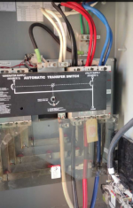
I was ask to look at this and comment. Sent to me from an apprentice that I had worked with. He told his journey man that it did not look correct and was told not to bother him any more about it. He told me it just did not look right.
With out giving to much info see if you can see what wrong.
It took me a minute to figure out what they did based on pic than I ask a few questions.
This is a service entrance rated transfer switch being used as one.
400 amp three phase 120/208 wye.
The green wires are a #4. I used word green as not to give it away right off the bat.
The parallel sets are 3/0 cu.
The single set is 500 mcm cu.
I told him to have his boss explain it to him.
To answer his question it wrong, red tag big time, epic fail.
 

Attachments

  • Screenshot_20220919-171420.png
    Screenshot_20220919-171420.png
    827.8 KB · Views: 104
If this is service equipment there should not be equipment grounding conductors entering from the supply side. There is a neutral to ground bond upstream of this transfer switch. Clearly this switch is bonded. You will have objectionable current flow on the ground and all grounded equipment between this switch and it’s supply.

Edit: I am an apprentice as well. I’m not sure if the #4 green conductors I am referring to would be EGCs or an equipment bonding jumper, or possibly another term without digging out a text book.
 
If this is the first disconnect point, assuming the 2 "green" are GEC, and based on there being a bonding jumper in place might assume that. Where are the EGC leaving the transfer to the distribution panel?

Second it appears no generator connections yet made. (Not a problem just an observation.)
 
Now look at it like this. If the utility landed conductors are service conductors with green wires and the load is a feeder with no green.
🤔
So I had ask which conductors come from the meter. Ones with no green or the set with green.
The ansawer was the 500 mcm is from meter. And the 3/0 are feeders to panel. 💥
So there is GEC and the EGC' are under sized.
Service conductors are landed on the load and feeders on the utility connection.
 
What? The whole thing backwards? That would never work for the generator to power the house, just backfeed the utility. If it even transfered.
 
What? The whole thing backwards? That would never work for the generator to power the house, just backfeed the utility. If it even transfered.
Who knows what they're trying to do. It doesn't appear there's a any connection to a generator anyway.

Maybe they are just using it as a disconnect for some reason. It would not work as a transfer switch as wired so likely somebody had something else in mind.
 
Now look at it like this. If the utility landed conductors are service conductors with green wires and the load is a feeder with no green.
🤔
So I had ask which conductors come from the meter. Ones with no green or the set with green.
The ansawer was the 500 mcm is from meter. And the 3/0 are feeders to panel. 💥
So there is GEC and the EGC' are under sized.
Service conductors are landed on the load and feeders on the utility connection.

No way we could know it's connected incorrectly without being able to ask the question you did. We have no idea where those green wires go. The transformer feeding this could be privately owned with the bond made at the transfer switch and not the transformer.
 
Who knows what they're trying to do. It doesn't appear there's a any connection to a generator anyway.

Maybe they are just using it as a disconnect for some reason. It would not work as a transfer switch as wired so likely somebody had something else in mind.
Line and Load are not marked correctly, therefore I believe it is a violation and a shock hazard for anyone who isn't aware its hooked up incorrectly. And there is the whole possibility of paralleling the generator with the utility if anyone ever managed to hook up a generator without getting shocked or causing an arc flash.
 
How's this for whistling in a graveyard?
  • One of the 2 sets of conductors on the Utility Supply terminals belongs on the Generator Supply terminals.
  • The other set of conductors on the Utility Supply terminals belongs on the load terminals.
  • The larger set of conductors now terminated on the Load terminals belongs on the Utility supply terminals.
  • Why the Service Entry or Service Lateral conductors are so much larger than the Generator Supply and Load conductors is beyond me!
  • Since the Main Bonding Jumper's terminal lugs were coded green that is a violation of the NEC because the use of Green color coding is reserved exclusively to Equipment Grounding Conductors (EGC's).
    • Although many inspectors don't see that distinction as important that doesn't make that use of Green color coding code compliant.
As somewhat of an aside I have a strong personal preference for keeping the Utility and generator conductors completely separated physically to completely minimize the possibility of a cross between them. Unless something has changed about the listing and NEC rules for transfer switches there is no requirement for that to be so but I usually went to the trouble of routing the conductors so that they did not have to share adjacent space with each other inside the transfer switch cabinet

Tulsa Electrician

When you are through playing with my head would you please let me know if any of my blatant guesses are anywhere near the truth? I'd appreciate knowing.

Tom Horne
 
Now look at it like this. If the utility landed conductors are service conductors with green wires and the load is a feeder with no green.
🤔
So I had ask which conductors come from the meter. Ones with no green or the set with green.
The ansawer was the 500 mcm is from meter. And the 3/0 are feeders to panel. 💥
So there is GEC and the EGC' are under sized.
Service conductors are landed on the load and feeders on the utility connection.
Impressive how wrong they got that one! Thanks for sharing.
 
Am i missing the gen conductors?
And the load ground?
I can't say what your missing since my name isn't "Claire Voyant." [I know it's lame but I couldn't resist the chance to do a pun so bad that I will get the groans out of my victims.]

On the top insulated terminals we have the 2 neutral conductors, of what I suspect are the generator and load conductor sets, a Main Bonding Jumper with the strange Green coded ends, with the 2 Equipment Grounding Conductors, one from the generator and one to the load, which terminate on the block which is bonded to the switch's cabinet. Once you include the three conductors on the load terminals; which I suspect are the utility supply conductors based on there being no EGC run with them, you have 2 EGCs, 3 neutrals, 3 sets of 3 phase conductors for the generator, utility, and load.

That's the count and the amount. What does he win?
 
Now look at it like this. If the utility landed conductors are service conductors with green wires and the load is a feeder with no green.
🤔
So I had ask which conductors come from the meter. Ones with no green or the set with green.
The answer was the 500 MCM is from meter. And the 3/0 are feeders to panel. 💥
So there is GEC and the EGC' are under sized.
Service conductors are landed on the load and feeders on the utility connection.
So your saying that the supply conductors from the Generator are not installed yet? Are the 2 sets of 3/0 "conductors in parallel" to the load? I don't see an Grounding Electrode Conductor (GEC) in that photograph. Is it, perchance, one of the 2 green wires with Green colored wire being used for the GEC in violation of the NEC? I like my guess better but only because it would be less wrong and easier to fix.
 
It appears to me the gen source terms are unoccupied... Who knows. Ill be there between 9am and 5pm on the 26th to fix whatevers wrong :) sorta helps to have a better view...
 
So your saying that the supply conductors from the Generator are not installed yet? Are the 2 sets of 3/0 "conductors in parallel" to the load? I don't see an Grounding Electrode Conductor (GEC) in that photograph. Is it, perchance, one of the 2 green wires with Green colored wire being used for the GEC in violation of the NEC? I like my guess better but only because it would be less wrong and easier to fix.
Just because you don't see a GEC in the transfer switch (or any 1st means of disconnect) doesn't mean there isn't one. Many POCOs require or permit the GEC to be in the meter. Some still require the connection at the weatherhead.
 
So your saying that the supply conductors from the Generator are not installed yet? Are the 2 sets of 3/0 "conductors in parallel" to the load? I don't see an Grounding Electrode Conductor (GEC) in that photograph. Is it, perchance, one of the 2 green wires with Green colored wire being used for the GEC in violation of the NEC? I like my guess better but only because it would be less wrong and easier to fix.
Yes it backward, load and utility. Confirmed.
No GEC installed as it the service disconnect.
EGC with feeders to small for the 400 amp breaker.
They were going to hook up gen today untill this very art apprentice decide to call the boss and have him explain this to him.
What caught my eye was the EGC's and no EGC or what ever with the 500.
Boss not very happy with j man that told him to mind his own business.
Good thing is, no one got hurt if this would have continued done it's path.
Here in Tulsa it's been my experience that not many inspector look that close and pass it which if power company would not have caught it may have been bad.

The 500 came right from meter and 3/0 right into a panel. The generator transfer switch is service rated and was being using as the service disconnect.
If I would have said EGC for the 3/0 most would have locked right in on it. Goes to show the correct words mean a lot.
Again just glad it all worked out for the better in this case.
 
Just because you don't see a GEC in the transfer switch (or any 1st means of disconnect) doesn't mean there isn't one. Many POCOs require or permit the GEC to be in the meter. Some still require the connection at the weatherhead.
Here in Tulsa for this power company it is require to have one from rids in the meter. City of Tulsa also require one in the service disconnect. What this pic did not show was the raceway to the transfer switch which was in metal and no bonding. This was a metal building. So a GEC system was required besides the rods and #6 to meter. In this case a good thing it was there.
 
Here in Tulsa for this power company it is require to have one from rids in the meter. City of Tulsa also require one in the service disconnect. What this pic did not show was the raceway to the transfer switch which was in metal and no bonding. This was a metal building. So a GEC system was required besides the rods and #6 to meter. In this case a good thing it was there.
What does "rids" in the meter mean?
 
Just because you don't see a GEC in the transfer switch (or any 1st means of disconnect) doesn't mean there isn't one.
I was only referring to another poster's including a GEC in the conductors visible in the photograph. Unless I misunderstood what he had typed which is not beyond the realm of the possible by any measure.
 
Status
Not open for further replies.
Top