208Y buck-boost

Status
Not open for further replies.

FionaZuppa

Senior Member
Location
AZ
Occupation
Part Time Electrician (semi retired, old) - EE retired.
I have 208Y and need 240 3ph to some machinery (wye wound motors). Manufacturer of the equip say 208v may work but the equip may have hard time starting. The building is multi-tenant from one poco 208Y xfrmer, so swapping out the xfrmer is not an ez option.

So, buck-boost to get the 240v needed. The equip motors are 3 wire 3ph (L1 L2 L3).

1) how does buck boosting from 208 to 240 'wire' into a 3 wire 3ph motor? Is the motor frame gnd pulled back to the wye neutral-gnd or is there a "gnd" in the buck boost?
2) what brand buck boosts are common/quality items (Larson, Schneider, other)?
 
Last edited:
Sorry, they are delta wound motors.
 
Hook up three boost transformers, one on each phase.
Ideally, they would have 19-volt secondaries, to bring the system up from 120Y208 to 139Y240. But I don't think they're available, so you'll need to select 24-volt secondaries (if your 208 runs a little low) or 16-volt secondaries. (if it runs a little high)

Connect the primary of each transformer from one phase to the white wire.
Connect the secondary of each transformer from the same phase to the motor.
(make sure to observe polarity; if you get one backwards you'll have 101 volts to neutral instead of 139)
After doing this three times, you'll have three phases for the motor, 240 volts phase-to-phase.
The white wire goes to the transformers, but not to the motor.

The frame ground (green, equipment-grounding conductor) is connected the usual way, to bond all the non-current-carrying metal parts.

The internal wiring of the motor is irrelevant. Just hook up three phases and an EGC.

- - -

Another option is swapping out the motor and installing one rated for 200-230 or 208-240 volts. It might be easier & cheaper than installing boost transformers, and it's the most-elegant solution.
If there's a control transformer in the machine, be sure to change the tap and configure it for 208 volts.
 
Hook up three boost transformers, one on each phase.
Ideally, they would have 19-volt secondaries, to bring the system up from 120Y208 to 139Y240. But I don't think they're available, so you'll need to select 24-volt secondaries (if your 208 runs a little low) or 16-volt secondaries. (if it runs a little high)

The machines have other smaller motors in them, but the thing is rated in spec sheet as 4hp 220v 3ph 60Hz. 220v is an odd voltage to call out.

I guess I really need pic of the the nameplates to know what specific buck-boost I should use. Schneider has a variety of boosts.

But let me ask, when I say 208 to 240 buck boost are you saying one BB per 120v phase (X-N, Y-N, Z-N), or do the BB's primary get connected across ph-ph (BB#1 XY, BB#2 XZ, BB#3 YZ) ?
 
But let me ask, when I say 208 to 240 buck boost are you saying one BB per 120v phase (X-N, Y-N, Z-N), or do the BB's primary get connected across ph-ph (BB#1 XY, BB#2 XZ, BB#3 YZ) ?


You can probably use a L-L connection using two transformers, just make sure that the 'load' does not have any L-N connections.
Every major manufacturer of Buck-Boost transformers will have a wiring diagram showing this.
 
You can probably use a L-L connection using two transformers, just make sure that the 'load' does not have any L-N connections.
Every major manufacturer of Buck-Boost transformers will have a wiring diagram showing this.

The 3ph equip is 3wire L1 L2 L3 and not 4wire L1 L2 L3 N, so no N on the load side. But I will get pic of nameplate prior to ordering the BB.

Thanks.
 
Last edited:
I connected a set for a customer a while ago. They had an imported milling machine that wanted 240 3ph and had a 208Y/120 3ph service.

Each BB (120/240) primary was connected in parallel for the 120v L-N, and each (12/24) secondary was connected in series for a 24v boost.

I wanted to wire the primaries in series and connect them in Delta, but the instructions insisted that the primaries be wired as a wye load.
 
. . . this one is a 208/240Y, i need 120/208Y BB
There is no such thing as a 208/240v primary. There will be two primary windings and two secondary windings. The primaries are connected in parallel for 120v and in series for either 208v or 240v.

If the 240v connection is supplied by 208v, the secondary voltages will be reduced by the same ratio. You then connect the secondaries in parallel or in series, depending on their voltage and your desired voltage.

my bad, I meant a 138/240Y, same as a 240 delta?


This Larson one says 208/240Y input? Seems odd, no?
https://www.larsonelectronics.com/p...primary-236-136y-secondary-12-5-amps-on-secon
 
Those are the ones I am looking at, but those BB's are 208 pri, that means they need to be connected to ph-ph of a 208Y (XY, XZ, YZ) if using one BB per ph boost. I am just curious how the secondaries of the BB's get connected to the load.

Looking at the drawing for that unit, it appears they use A and C phase to power the transformers and let B phase pass to the load w/out modification. So it's just 2 transformers not 3.
 
but this one is a 208/240Y, i need 120/208Y BB

Why? You don't need a neutral, so ... why?

I think you would have 240 with the voltages to ground being 156, 120, 156. This should not be a problem unless you try to use the neutral and A or C phases. You are going to one piece of equipment, right? I think this does it for you (if it's the right size).
 
190422-2000 EDT

oldsparky52:

I believe your 156 is in error.

We have a vector triangle of 120 V for one side and 240 V for another side, and 60 deg between these two sides. What is the length of the third side?

Break this into two right triangles. One triangle has 120 for the hypotenuse, and the other two sides are 60 ( from (sine 30) 0.5*120 ), and 103.92 ( from (cos 30) 0.866*120 ). Thus, the other right triangle is 240-60=180 for one side, and 103.92 for its second side. The hypotenuse, our desired value, is the sq-root of ( 180^2 + 103.92^2 ) = sq-root of ( 32400 + 10799 ) = 207.9 .

207.9 or 208 is not 156.

.
 
Why? You don't need a neutral, so ... why?

I think you would have 240 with the voltages to ground being 156, 120, 156. This should not be a problem unless you try to use the neutral and A or C phases. You are going to one piece of equipment, right? I think this does it for you (if it's the right size).

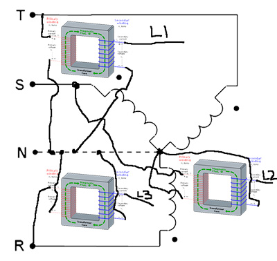
If the service is 120/208Y then the BB needs to match that on it's input, regardless of N. If i stick a BB on each phase (L-N) and boost each to 136v, ph-ph on sec BB side will be 240v. My Q is, if the BB sec is a coil then does one side of each sec coil get tied down to the Y N making a common ref point for it all for the BB xfrme to boost, but then I just take one wire from each BB as my L to the equipment (L1 L2 L3)?

like this, which is basically a mini step-up 120-->138v xfrmer on each phase of 208Y using common N for the coils. L1 L2 L3 would be brought to the equipment.

ddd.jpg
 
190422-2029 EDT

The boost operation of the two transformers in the reference of post #7 by oldsparky52 takes a line to line voltage of 207 and adds to this to get 240.

This 240 is referenced to a line, such as B. For example Vab has the added voltage added at the line A end. With another transformer this is done for Vcb. Call these new lines A' and C'. Va'b is 240, and Vc'b is 240. A new triangle is created with Va'b, Vc'b, and Va'c'. The original triangle from Vab, Vcb, and Vac was an equilateral, and so is the new one. But line to neutral voltages are unbalanced in the new compared to the original.

.
 
190422-2105 EDT

FionaZuppa:

I can not understand your diagram. But I don't believe you drew a circuit that would be described as a boost circuit.

A boost circuit using three transformers to create a balanced wye system would for each line to neutral phase have the primary of the boost transformer connected from its line to neutral and then its secondary would connect from its line to the new output line so phased that the voltages add.

.


the 208Y has X Y Z N, N being common to X Y Z. XY YZ ZX all measure 208v. XN YN ZN all measure 120v. The ph diff between X Y Z is 120degrees.

I can place a step-up xfmer (primary side) onto XN YN ZN (hence 120v primary), or, I can place the step-up primary across XY YZ ZX (hence 208v primary).

With that said, both setups still have 120 degree ph diff. So if I connected 3 step-up xfrmer's, each xfrmer would have two wires sticking out on the secondary side, so how do those secondary wires get connected? Each xfrmer secondary will measure 240v, so in essence you achieve 3 one ph 138v or 240v supplies, but how do you wire the secondaries so that you can use those secondaries to feed a 3ph delta motor L1 L2 L3?

The pic i posted is a step-up from 120 to 138v, basically a wye-wye step up w/ N as the common to both primary and secondary coils.
 
190422-2000 EDT

oldsparky52:

I believe your 156 is in error.

We have a vector triangle of 120 V for one side and 240 V for another side, and 60 deg between these two sides. What is the length of the third side?

Break this into two right triangles. One triangle has 120 for the hypotenuse, and the other two sides are 60 ( from (sine 30) 0.5*120 ), and 103.92 ( from (cos 30) 0.866*120 ). Thus, the other right triangle is 240-60=180 for one side, and 103.92 for its second side. The hypotenuse, our desired value, is the sq-root of ( 180^2 + 103.92^2 ) = sq-root of ( 32400 + 10799 ) = 207.9 .

207.9 or 208 is not 156.

.

Nevermind, I checked my drawing and now it shows something different than I said. so, .... :ashamed1:
 
Last edited:
Status
Not open for further replies.
Top