208Y buck-boost

Status
Not open for further replies.
I us a CAD drawing and drew a line from 0, 120 units away on 0 deg line. Then I drew a 120 unit line from 0 on both the 120 and 240 degree lines. I extended those lines. Then I drew a circle from the 120 unit end of the 0 degree line and that circle had a radius of 240 units. Then I measured from 0 of the 120 degree line to the intersection of that line and the circle drawn earlier. That was 156.33 for both the 120 and 240 degree lines, and of course the 0 degree line did not change. The measurement between the 156.33 points of the 120 and 240 degree lines equaled 240.

What did I do wrong? What am I thinking of incorrectly?

on a 3 spoke wheel w/ 120deg between each spoke, each leg is 120 units long, but the long side is 120 sqrt-3, 208v.

Your CAD should have this correct. The Long side (ph-ph) is always ph*sqrt-3 for a 120deg 3 spoke.

Capture.png
 
190422-2000 EDT

oldsparky52:

I believe your 156 is in error.

We have a vector triangle of 120 V for one side and 240 V for another side, and 60 deg between these two sides. What is the length of the third side?

Break this into two right triangles. One triangle has 120 for the hypotenuse, and the other two sides are 60 ( from (sine 30) 0.5*120 ), and 103.92 ( from (cos 30) 0.866*120 ). Thus, the other right triangle is 240-60=180 for one side, and 103.92 for its second side. The hypotenuse, our desired value, is the sq-root of ( 180^2 + 103.92^2 ) = sq-root of ( 32400 + 10799 ) = 207.9 .

207.9 or 208 is not 156.

.

Did you just calculate the voltage for a 208Y system?

What happens to the angle if only 2 phases are boosted?
 
on a 3 spoke wheel w/ 120deg between each spoke, each leg is 120 units long, but the long side is 120 sqrt-3, 208v.

Your CAD should have this correct. The Long side (ph-ph) is always ph*sqrt-3 for a 120deg 3 spoke.

Capture.png

When I boosted 2 phases the voltage did go to 156 to neutral, but ... the voltage between the 2 boosted phases was more like 270 when the voltage from a boosted phase to the non boosted phase was still 240.

So, most likely I don't know what I'm doing.
 
190422-2448 EDT

In post #7 the reference is to the use of two boost transformers applied to either a delta or wye source, doesn't matter.

A boost (buck) transformer is one where the primary is supplied from a full voltage source, and an isolated secondary either adds or subtracts from, generally, that same source.

An autotransformer might be considered as a self-contained buck or boost transformer.

Some of the posts above seem to be describing a setup transformer. There is a big difference in VA capability for a given size transformer for most applications.

Where you get the buck or boost primary from and how the secondary is related determines your result. Generally you only want a 0 or 180 deg phase shift.

.
 
In post #7 the reference is to the use of two boost transformers applied to either a delta or wye source, doesn't matter.
It does only if you need a balanced neutral reference; i.e., same voltage to neutral (ground) on all three lines.
 
208 to 240V Boost Transformer Setup

208 to 240V Boost Transformer Setup

I have 208Y and need 240 3ph to some machinery (wye wound motors). Manufacturer of the equip say 208v may work but the equip may have hard time starting. The building is multi-tenant from one poco 208Y xfrmer, so swapping out the xfrmer is not an ez option.

So, buck-boost to get the 240v needed. The equip motors are 3 wire 3ph (L1 L2 L3).

1) how does buck boosting from 208 to 240 'wire' into a 3 wire 3ph motor? Is the motor frame gnd pulled back to the wye neutral-gnd or is there a "gnd" in the buck boost?
2) what brand buck boosts are common/quality items (Larson, Schneider, other)?

To get 240V 3Φ 3W from 208Y 4W, you only need 2 transformers. The system ground from the 208Y, would ground the 2 transformer cases, and pass on through, to the load connection. This is standard for machine loads that do not require a neutral connection.

This arrangement is called an open delta, and uses 2 small transformers, with a wiring trough underneath to make the connections. The output is a open delta configuration, and the input is from a Y configuration, minus the neutral.

You should check with the machine manufacturer that the machine does not require a neutral, and does not need a symmetrical neutral reference. Machines that have VFD's or other drives, usually require a symmetrical Y input, which would require a symmetrical Y 3 transformer boost system output.

Larry provided you a drawing of a Y system, if that is what you require. If the machine has no VFD drives, you likely can use the open delta configuration with just two transformers.

The open delta's output voltages are not symmetrical with respect to ground, but that doesn't matter if all the machine has is electromagnetic controls and across the line motors.

Common brands are Acme (now Hubbell), Jefferson, Eaton, Federal Pacific, Hammond, HeviDuty, Dongan, Siemens, SquareD

Here is a setup for a automatic plasma cutting table. Going from 208Y to 240V Open delta. These were Jefferson units.

BoostTransformer1.jpg

BoostTransformer2.jpg

208 to 240 Boost Diag.jpg

Here is some reference material from Dongan. Look partway down the page for downloadable selection tables and connection diagrams.
https://dongan.com/product-category/buck-boost/

MTW Ω
 
Basically just Google "buck boost transformer calculator", select you voltages and kva and it will give you a part number and wiring diagram. Easy as that. IIRC, they will pretty much all tell you to go open Delta if you don't need neuter.
 
Since your load doesn't require a neutral, you don't care what end resulting line to neutral voltage is. You are boosting 208 to 240 volts.

A buck-boost transformer is an autotransformer. before getting into boosting voltage for all three phases take a look at how you would boost a single phase 208 volts to 240 volts with a single autotransformer. You essentially connect the high voltage winding and the low volt winding in series in a manner to effectively get a single winding with multiple voltage taps. There is no primary and secondary like there is for an isolation transformer, just several taps that you can achieve different voltages from depending on how you connect them.

Equipment grounding is accomplished by the EGC of the supply circuit - there is no isolation and need for establishing a secondary grounded conductor like there is for a separately derived system.

Output volts to incoming neutral will not necessarily be equal either. For simple single phase 208 to 240 boost, one line will be direct connection to one of the input lines - and will still be 120 volts to ground, the other will be offset by the amount of boost and will be 152 volts to ground.
 
Last edited:
190423-1203 EDT

Going back to the first post
So, buck-boost to get the 240v needed. The equip motors are 3 wire 3ph (L1 L2 L3).
it is stated that the motors are 3 wire. Thus, it does not matter much whether the source is wye or delta or how it is referenced to earth.

The source could be 1,000,000 volts off from earth, and breakdown voltage might be problem.

How do you get 156 V to neutral? What is your calculation?

.
 
For clarity, "Line" in this pic means the lines X,Y,Z coming off of a 208Y xfrmer? So 1-->2=208v, 1-->3=208v, and 2-->3=208v.

How does connecting some coils in series (with taps) across the lines of 208Y (208v) cause a voltage increase in the chain of coils? I assume this pic (1=3)>2 when ref'd to the 208Y N/gnd?
 
When I boosted 2 phases the voltage did go to 156 to neutral, but ... the voltage between the 2 boosted phases was more like 270 when the voltage from a boosted phase to the non boosted phase was still 240.

So, most likely I don't know what I'm doing.

Yes indeed. but if the ph-ph voltage is not consistent wont a 3ph motor "buck" @ the driven frequency? All 3 need to be boosted to 138 if using this method.

Capture.png


Capture.png
 
Last edited:
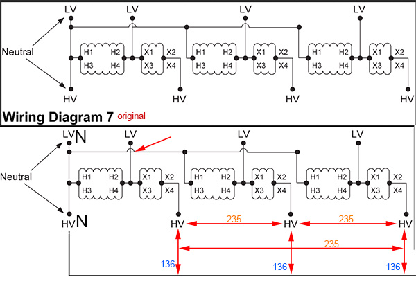
Here's a Schneider example (■D part #). They boost each phase if the source is a 4wire 120deg WYE.

In the wiring pic I included their original from their online tool. The red arrow appears to be a mistake, should be a full jump-over there.
She even highlights the problem area but never corrects the issue. I wonder how many try to wire it as shown in their pic? (https://www.youtube.com/watch?time_continue=128&v=C7iJmkmLP0M), that dreaded "hmmmmmmmmmmmmm, pop" sound

schneider1.png


boost-1.jpg
 
Last edited:
Schneider will be fixing their bad wiring diagram #7 !! :)

.... maybe. I made them (xfrmer engineer) aware of the issue, so who knows if they'll fix it.
 
Last edited:
Here's a Schneider example (■D part #). They boost each phase if the source is a 4wire 120deg WYE.

In the wiring pic I included their original from their online tool. The red arrow appears to be a mistake, should be a full jump-over there.
She even highlights the problem area but never corrects the issue. I wonder how many try to wire it as shown in their pic? (https://www.youtube.com/watch?time_continue=128&v=C7iJmkmLP0M), that dreaded

You could use the "three-phase open delta" on the Scneider Calculator rather than the "three-phase wye" option.
 
Status
Not open for further replies.
Top