208Y buck-boost

Status
Not open for further replies.
No, I would say a three-phase transformer, electrically equivalent to three single-phase transformers.
Electrically equivalent in some ways, like voltage ratios and magnetizing current, but I believe that it behaves very differently when it is not symmetrically fed, such as when one primary phase or line is open.

Sent from my XT1585 using Tapatalk
 
190424-2014 EDT

oldsparky52:

Your phasor drawing of of post #66 is just fine and describes the end result.

It might have been clearer with lines drawn between the original line to line points because it would visually show the added voltages to be in phase with the line to line voltages from which the added voltages are derived.

You could also draw lines from the new line points, the ones I called ', to the neutral point and measure these lengths.

You are using a graphical approach to solving the problem and that is a good method.

.
 
Somewhat crude, but this is how I now understand the 2 transformer set up.

(substitute volts for inches)
I think it is fairly close to correct though. Not sure if the added volts should continue in straight line or if should divert like you drew it.

The dark Y in the center is representative of the source, if you draw a line from the two ends that the boost transformer is connected to, you would draw the "open delta".

Notice the source neutral is not at the neutral point of the delta.

It is still 120 units from the point that has no boost transformer connected to it - one could run a 120 volt load from that point and the neutral if needed (maybe a control circuit?)
 
190424-2354 EDT

kwired:

oldsparky52's drawing is correct because you want to use 208 as the primary because you want to preserve phase and have the source and its added voltage have 0 or 180 phase shift linearly add. Then the end result has no phase shift relative to the original 208. That is not well worded but I think it says what I want it to say.

This is why I suggested that
oldsparky52 should add into the drawing the 208 phasors to show the linearity of the source (primary) and its secondary.

.
 
190424-2430 EDT

kwired:

Suppose I have a 120 V to 32 V boost transformer with the primary fed from A to N. The 32 V is added to A. What is the voltage from A' to B and the phase shift of A' to B relative to A to B? Consider A to B to have an angle of 0.

Again it is a triangle solution. ( (208+32*0.866)^2 + (32*0.5)^2 )^0.5 = 236.25 . The angle difference is arc sine 16/236.25 = 3.9 deg.

This angle difference may not be a big problem, but it is a shift, and if the added voltage was greater the shift would be greater. The motor torque ripple will be slightly higher, but nothing like that of a single phase motor.

.
 
190424-2014 EDT

oldsparky52:

Your phasor drawing of of post #66 is just fine and describes the end result.

It might have been clearer with lines drawn between the original line to line points because it would visually show the added voltages to be in phase with the line to line voltages from which the added voltages are derived.

You could also draw lines from the new line points, the ones I called ', to the neutral point and measure these lengths.

You are using a graphical approach to solving the problem and that is a good method.

.

Thank you gar, and thanks for your help through this understanding.
 
You do not pull a neutral to the transformers. There is no reason to and it may cause problems.

Whaaaaa? Wiring diagram #7 that Schneider has (posted a few back) must use the N from the Y source. They are boosting phase voltage from 120 to about 136. There is no way to achieve that using the wye 3-xfrmer config when boosting the phase voltage. You can use a 3-xfrmer setup using line voltage from the Y, which can derive a new neutral or be tied back to the Y source N. I will show that later
 
Whaaaaa? Wiring diagram #7 that Schneider has (posted a few back) must use the N from the Y source. They are boosting phase voltage from 120 to about 136. There is no way to achieve that using the wye 3-xfrmer config when boosting the phase voltage. You can use a 3-xfrmer setup using line voltage from the Y, which can derive a new neutral or be tied back to the Y source N. I will show that later
That is one way to do what you want to do, boost each existing 120 volt coil. The open delta method mentioned is another way, and would cost less because you only need two units instead of three. A typical three phase motor (wye or delta wound) should work either way, it only cares about line to line voltages and has no connection to the neutral of the source.
 
Whaaaaa? Wiring diagram #7 that Schneider has (posted a few back) must use the N from the Y source. They are boosting phase voltage from 120 to about 136. There is no way to achieve that using the wye 3-xfrmer config when boosting the phase voltage. You can use a 3-xfrmer setup using line voltage from the Y, which can derive a new neutral or be tied back to the Y source N. I will show that later
You don't need any 120V boosted to 136V. That is meaningless. You need 208V boosted. Line to line voltage is all that matters to the motors.
 
190425-1110 EDT

There are several ways to boost a 120/208 wye to a 240 delta.

One is to use two or three isolation transformers to create a delta, open or closed. Three isolation transformers can create a wye secondary. All these preserve phase angles.

A single auto or boost transformer from one line to neutral source can provide 3 phases. But voltages are not balanced, and angles are not preserved.

Two transformers can provide a balanced open delta, and preserve phase angles, but not line to neutral voltage.

Three transformers allow for a number of possibilities.

.
 
You don't need any 120V boosted to 136V. That is meaningless. You need 208V boosted. Line to line voltage is all that matters to the motors.
But you can get that voltage either by boosting the line voltage (primaries fed L-N) or boosting the phase voltage (primaries fed L-L). In either case the boost coil is in series from L to L', the new terminal to motor.
In the first case a balanced connection is preslferred, but a two transformer version would have unbalanced voltages a d phase angles . In the second case likewise, three better, but for open delta you must not connect the third L to the third L'. The open delta will be balanced, subject to standard open delta problems.

Sent from my XT1585 using Tapatalk
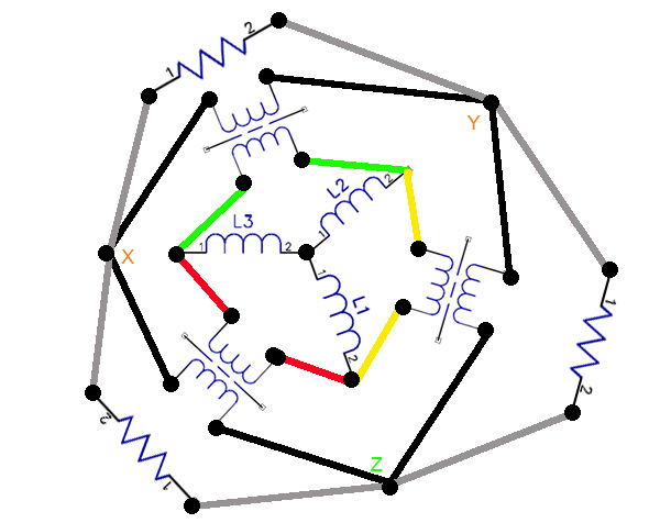
 
Does this work? Pros or Cons ? The xfrmers hanging on the lines are step-up's

Untitled-1.jpg
 
But you can get that voltage either by boosting the line voltage (primaries fed L-N) or boosting the phase voltage (primaries fed L-L). In either case the boost coil is in series from L to L', the new terminal to motor.
In the first case a balanced connection is preslferred, but a two transformer version would have unbalanced voltages a d phase angles . In the second case likewise, three better, but for open delta you must not connect the third L to the third L'. The open delta will be balanced, subject to standard open delta problems.

Sent from my XT1585 using Tapatalk
Two or three transformers matters not a whit. One is only needing to boost the voltage line to line. Anything else is fine for a ethereal discussion of a useless magnitude of the highest degree, which is what this thread is.
 
190425-1441 EDT

FionaZuppa:

Both your circuits work, but neither is a buck or boost.

.

Ok, so why would I choose a BB over a L-L or L-N step-up, or vice versa?
 
190425-1731 EDT

FionaZuppa:

Think about the problem.

If the primary of your transformer is full supply voltage, and you step up to an output voltage 10% higher, and this is supplied by a separate winding, then that transformer has to have a VA capability equal to the total load.

If instead the transformer is an autotransformer, or a boost transformer, then the boost portion only has to supply the 10% higher voltage at the same current as the basic source. Thus, a boost transformer size in most appliations is much smaller than if an isolation transformer was used to do the same task. Usually boost voltage is not large compared to the source voltage.

.
 
125% of the rated input current (or next size up, if over 9A) is the MAXIMUM overcurrent protection for an autotransformer.

35A would be the largest OCPD allowed.

That is the correct percentage (125%) for a autotransformer primary protection. It was late and I didn't take time to look. Used from memory the 250% limit on isolation models, with primary and secondary protection.

MTW Ω
 
Status
Not open for further replies.
Top