240v debate....

Status
Not open for further replies.
With the circuit that Besoeker has, the load current in the winding halves will only flow from the center to the ends of the windings and will never flow from the ends towards the center-tap. One half will flow in one direction and the other half will flow in the other direction.

That is not the case without the diodes.

NO NO NO NO I am not talking about diodes I am talking about a single phase center tapped transformer of 120/240 volts. I need to keep it simple so my weak mind can understand. The two of you have about got me convinced so don?t start mudding the water now.

With the pumps drawn above where the two pumps are opposing each other my simple mind says that there is going to be a vacuum drawn and both pumps will shut down just as two opposing voltages will cancel each other out and no current will flow just as turning one battery backwards in a flashlight the light won?t come on.

Help me to better understand please
 
Flemming's left and right rules generally relate to (DC) motors and generators respectively hence the thumb for motion. One wouldn't ordinarily expect much motion within a transformer under normal operating conditions.

Are you really saying the principles of electro-magnetism do not apply to a transformer?
So, would my position be acceptable if I was talking about a single center tapped generator winding?
 
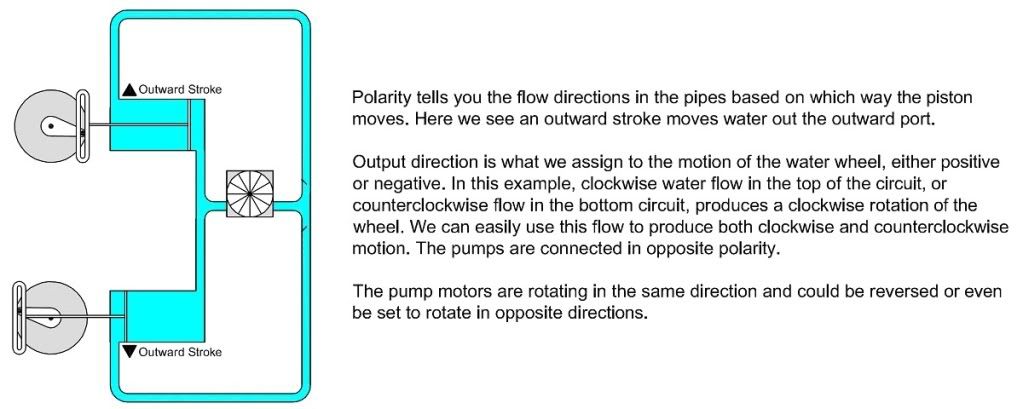
I made some water wheel graphics that illustrate Besoeker's circuit.

This is his circuit with the pumps in polarity. You will notice that the water in the top half only circulates clockwise and the water in the bottom half only circulates counterclockwise. That is because of the one-way flapper valves (diodes). It might be hard to see at this resolution but the flapper vales pivot on the left side and are open on the right side.

Waterwheelrectifiedwithsamepolarity.jpg


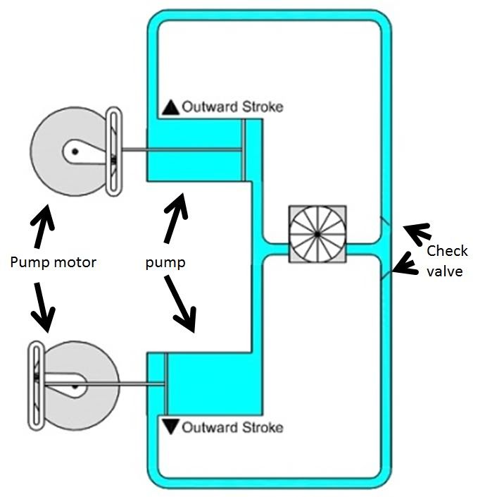
Here is the same circuit but using pumps connected in opposite polarity:

Waterwheelrectifiedwithoppositepolarity.jpg

Top picture
Water will leave the top pump and hit the check valve and stop
Bottom pump water will leave the pump go through the middle pipe and disperse through both check valves

This is of course if the valves are installed as shown

Bottom picture neither of the pumps will be able to pump anything as the check valves stop water flow from either pump

This is of course if the valves are installed as shown
 
It is a series circuit. A two-terminal circuit (the 3rd terminal does not enter the picture for the two-wire circuit) is not the same as a three-terminal circuit.
Do you actually change your theory based on the number of terminals you are using, or are you only changing the math?

I don't really think you just ignore those parts of the world that conflict with your position, it seems you must solve those issues independently (i.e. treat the source as a black box), but honestly I am not sure.

And for those of you just tuning in.
I fully admit the math that says: -van+Vbn=-Vab
 
You simply refuse to acknowledge the physics of a transformer, because it conflicts with your position that the circuit should be solved using the neutral point to define voltage direction.
You keep quoting me as saying should but I keep telling you I am using the word COULD. I am not breaking any electrical theory laws. Van and Vbn are mutually displaced by 180? and they are real volatges and do not break any laws when taken that way.

If the construction of a single core transformer is of no concern then why are there industry standards regarding the designation of the terminals? Why do we care about polarity dots when connecting transformers?
Polarity and direction are related but are not the same thing.

ANSI standards say that when current is flowing into H1 a corresponding current is flowing out of X1 doesn't this then define a direction?
That defines a relative direction, not that one or the other is right or wrong or real and not real.
 
NO NO NO NO I am not talking about diodes I am talking about a single phase center tapped transformer of 120/240 volts. I need to keep it simple so my weak mind can understand. The two of you have about got me convinced so don?t start mudding the water now.

With the pumps drawn above where the two pumps are opposing each other my simple mind says that there is going to be a vacuum drawn and both pumps will shut down just as two opposing voltages will cancel each other out and no current will flow just as turning one battery backwards in a flashlight the light won?t come on.

Help me to better understand please
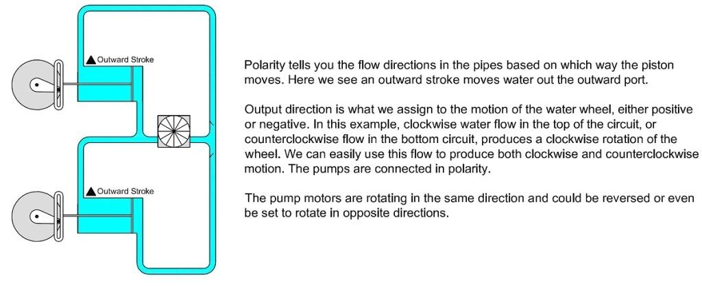
Look at the position of the pump motors. Rotate the motors in the same direction, say counter clockwise, and draw some arrows indicating the motion of the pump arm and the water flow. Let me know if that doesn't work and I can make some additional pictures or add some arrows.
 
Top picture
Water will leave the top pump and hit the check valve and stop
The flapper valve has a hinge point on the left so it will rotate clockwise and the opening on the right will get bigger as the flow increases.

Bottom pump water will leave the pump go through the middle pipe and disperse through both check valves...This is of course if the valves are installed as shown.
The valves open the other way. You can see it if you zoom in about 400%. It was clearer with higher resolution.
 
Do you actually change your theory based on the number of terminals you are using, or are you only changing the math?
The theory does not change. What you are not seeing is that the theory works for voltages in both directions.

I don't really think you just ignore those parts of the world that conflict with your position, it seems you must solve those issues independently (i.e. treat the source as a black box), but honestly I am not sure.

And for those of you just tuning in.
I fully admit the math that says: -van+Vbn=-Vab
But do you agree that the sources in my post #98, where everything is using the Earth for a common reference, have real (not just math tricks) voltages from X1 terminals that are displaced by 180??
 
The valves open the other way. You can see it if you zoom in about 400%. It was clearer with higher resolution.
I made the opening larger and re-uploaded to make it easier to see but it will probably take a day for Photobucket to refresh.
 
The flapper valve has a hinge point on the left so it will rotate clockwise and the opening on the right will get bigger as the flow increases.

The valves open the other way. You can see it if you zoom in about 400%. It was clearer with higher resolution.

Am I missing something here?

pumps.jpg
 
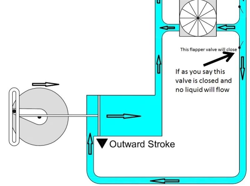
Try this:

Waterwheelcloseup.jpg

Your bottom pump is flowing against the grain or in opposition to the flow as indicated by the flow arrow at the bottom and against the check valve in the bottom half.

Maybe we should stick to electricity instead of trying to do plumbing although the directions you indicate the liquid is flowing is the same way electricity flows through a center tap transformer
Your direction of liquid flow shows a 120 volt and a 240 volt flow at the same time. Notice how the liquid is all flowing in the same direction and there is no 180 degree shift anywhere.
 
Your bottom pump is flowing against the grain or in opposition to the flow as indicated by the flow arrow at the bottom and against the check valve in the bottom half.
You will note the the bottom pump has just started to move inward and the bottom valve is in the process of shutting. This example is only good for those familiar with water flow. If you are not, it will not help you.

Maybe we should stick to electricity instead of trying to do plumbing although the directions you indicate the liquid is flowing is the same way electricity flows through a center tap transformer
More specifically, the way the current is flowing at a particular point in time.

Your direction of liquid flow shows a 120 volt and a 240 volt flow at the same time. Notice how the liquid is all flowing in the same direction and there is no 180 degree shift anywhere.
If you can't see that the pump arms are moving in different directions, this graphic is not going to help you at all. I suggest you forget it.
 
chrckvalve.jpg


Been doing hydraulics for many years now and even have a small lab in which we can set up this drawing and see that it will not work.
You're correct. He is trying to show a "DC" flow through the neutral, but in the process has each pump in a locked-piston condition for each half-cycle. He tried to make it look like the diode electrical diagram, but it doesn't work quite that way. He does have a DC flow in the neutral, but you have to study it pretty hard (and ignore the locked-piston condition) to spot it.
 
Been doing hydraulics for many years now and even have a small lab in which we can set up this drawing and see that it will not work.
So why do you say it won't work? Are you concerned with the low pressure in the bottom part of the circuit that will develop or what? Are you saying that makes it a deal-killer as an illustration?

I have already addressed the issue you had when you thought the valves were turned the other way. I'll admit I'm not hydraulics expert so it is entirely possible that there is something I'm missing. Enlighten me.
 
. Enlighten me.
your check valves are not in the right order for the flow to work as you say it is working.

lets stay with a single phase transformer and leave the plumbing out as what you have drawn will not work as you are wanting it too

Edited to add

You seem to be having hard enough time understand the function of a single phase center tap transformer so understanding how fluids flow throughout a fluid system is going to be hard on you also.
 
Last edited:
Are you saying we can't overcome the pressure issue? Even with a pressure bladder or something similar? How does that impact the flow directions as shown?
If not a pressure bladder, how about a compression spring in the the pump shaft that will keep the pump motor from over-loading?
 
If not a pressure bladder, how about a compression spring in the the pump shaft that will keep the pump motor from over-loading?
Then the piston will never move---ever.

If you really wanted to do this, you would have your check valves in the face of the pistons.
 
Status
Not open for further replies.
Top