240v debate....

Status
Not open for further replies.
I hate to say it but in the real world Rick is correct, we have been accustom to using the phrase 180? for a long time to explain such things as canceling out fields in conduit and transformers in how the work, but in reality the voltage supplying a "single phase load" comes from only one single source that only has a + terminal and a - terminal it is a single pole in a generator that gives us this source and is no different then if it was a single battery being rotated 60/50 times a second it has the same + and - this pole in the generator has, the reason Rick is stating that one end of the transformer or the center tap is never out of phase is it's not, take a point in time when X1 is full positive and X2 will always be at full negative, this reference in time will never change,and when X1 is full negative X2 will be full positive this relation between X1 and X2 will always stay the same, now in a Polly phase system you have introduce an offset in the time when the second pole X1 reaches full positive and its X2 reaches its full negative again the reference between X1 and X2 of pole 2 will alway happen at the same time on the rotation of the 360? of the armature, but now you have inserted a vector delay between pole one and pole two it can be 120? or 90? depending upon the system, but it now has rotation and a phase angle, this rotating angle cannot be created by a transformer alone.

I tried to point this out in the thread awhile back when we we discussing the terminology of single phase and why it was not called two phase, I tried to point out that if you think of the source at any time you are connected to just two conductors of a 3 phase system you are only connected to one pole of the generator, take a three pole generator (simplified) each pole will have two conductors coming out of the pole, with 3 poles 120? apart you will have 6 leads connect them together to form a delta, now draw three lines one from each of the connection point if you connect to only two of those conductors you will only have one pole of that generator connected to the load, you will have a positive voltage on one and a negative voltage on the other that will swap 60 times in one second but in perfect sync not out of phase.

Saying one conductor is 180? out of phase with the other would have the same meaning of saying that one end of a battery is 180? out of phase with the other just because one is positive and the other is negative.

I know I'm a little rusty in the way of explaining this, but hammer away:p
 
Last edited:
I think I remember being explained to me that the 180? came from a single phase generator and when one end of the pole of the armature was near the north pole field the other was near the south pole field as the armature rotated 180? the polarity swapped which is where we got the term 180? out, but not out of phase as there is no other phase.

While this might not be the correct reason but it sounds good:p
 
Safer when talking risk of electrocution. I have heard many windmill accident stories. Some ranchers with remote pastures still use them for pumping water for cattle. I know a well man that fell off one, was in hospital for long time but did recover.


.

Would that be as opposed to a sick man?:blink:
 
I will debate that claim, by simply stating that dead is dead, and "electrocution" means dead. And if you meant that higher voltage gives a more severe shock, then I will restate that 120V and 240V will make you equally dead, and no less dead than 60V would have made you. Neither 120V nor 240V is "safer" than the other. That is the essence of the original question.

If you do not have a direct contact, eg. via gloves or through clothing the resistance will make the difference whether it will be a lethal shock or not.
 
And I refer you to the posting directly above the one you just made. If your phase shift was real, then putting a diode on the primary will result in the shift I described.
No it wouldn't and I would advise against trying it. The resulting unidirectional current would saturate the transformer. Any engineer ought to understand that.

The situation you described is nothing more than a canceling of magnitudes.
They would not cancel unless those magnitudes were equal and opposite.
i.e 180 deg phase shifted from each other.

It does not prove your point, and that is why I did not comment on it when you made it. If you want me to comment on these things, then you need to put some more thought into them before making them. It was not well thought out and I do not have the patience for that, as you may have noticed.
And, if you want to refute my points, you need to etc.......
 
I hate to say it but in the real world Rick is correct,
Not really.
Here's a simple diagram to illustrate the point I made about neutral current in post #49. It's one I've posted previously.

240Vsingle-phasebalanced.jpg


Unless the 120V supplies were in anti-phase i.e. 180deg apart, the neutral current would not, and could not, be not be zero.

As I said, I posted this before so I thought I might just add another to consider. It is a simple rectifier circuit. Just a centre-tapped transformer and two diodes.

Rectifier01.jpg


And this how the output current looks:

Rectifier02p.jpg


Note that Ia and Ib are displaced by 180deg.Another that may be a little more striking is the same circuit but with SCRs.

Controlledrectifier01.jpg


Output:

Rectifier01p.jpg


Note that the two SCRs HAVE to be triggered 180deg apart because the voltages are 180 deg apart.

I don't know what else I can do to make the point.
 
Besoeker,
The reason why your examples are showing exactly what you/we would expect is because they are simply loads acting on the output of your transformer after your alleged phase shift.

If you wanted to prove that your phase shift existed or not, then simply move the diodes to the primary side of the windings. This places them upstream from your alleged phase shift.

If your phase shift was real (as you allege), then your output graph will still look like the image below. Your Ian and Ibn signals would each be half-wave rectified, and your combined Iab signal would remain an un-rectified AC signal.

If your phase shift was not real (as I say), then your Ian and Ibn signals (labeled Ia and Ib) would both be occurring in the first 180? of your output signal, and your Iab combined waveform will also remain half-wave rectified. It won't be perfect rectification because at 180?, there will be an artifiact from the collapsing of the magnetic field. Nevertheless, this is sufficient to demonstrate a waveform that is non-symmetrical about pi (180?).
Rectifier01.jpg


And this how the output current looks:

Rectifier02p.jpg
 
Besoeker,
I put together a graph of what I am describing. You can confirm this mathematically or with your scope.

The input on the primary is pretty straightforward. On the secondary, if there is a phase shift, then the two waveforms for VAN and VBN will be shifted 180? as you claim. Putting them together will result in the lower VAB waveform shown. This represents getting full-wave rectification with just a single diode.

On the other hand, if there is no phase shift, but simply a polarity reversal in magnitude, then the upper output waveform is what will be true, and you will have the typical half-wave rectification, where the voltage is zero (almost zero) between 180? and 360?.

PhaseShiftTransformer.jpg
 
By the way, even though the diagram was not intended to be technically perfect, I did notice a significant error in the output waveform representations (simple copy/paste error).

If the two halves were phase shifted, the magnitudes would not have added in each peak. They would have been closer to the peak values of each individual waveform.

PhaseShiftTransOut.jpg
 
Besoeker,
The reason why your examples are showing exactly what you/we would expect
My examples are precisely what happens regardless of what you or I expect.
Your diagram in post #88 shows a diode in series with the primary winding.
Can't you see that the resulting direct current will saturate the transformer?
 
Last edited:
My examples are precisely what happens regardless of what you or I expect.
Your diagram in post #88 shows a diode in series with the primary winding.
Can't you see that the resulting direct current will saturate the transformer?
That is not DC. It is a half-wave rectified, time varying signal. Your reiteration of this response has me a little concerned that I'm not dealing with a full engineer. I can't ask you that question, but I can remind you that I am not an engineer just by job title.

As for your examples, no, they do not show a thing. You have one diode that is acting on the 0? to 180? half waveform, and the other diode acting on the 180? to 360? half waveform. It is a standard full-wave rectifier utilizing a center-tapped transformer.

I don't care if your transformer is saturated. The principle will remain the same. If that's a concern to you, then cut the voltage, or model it with an ideal transformer. Where in my discussion or diagram are you seeing a primary voltage reference or a transformer rating? The principles are the same regardless whether it is a 1MVA or 1mVA transformer. Go to Radioshack (or the UK equivalent) and pick up a small center-tapped transformer and connect it to your signal generator.

Instead of dismissing the example on your false assumption it will saturate your transformer, look at it from its intended purpose of removing the symmetry from your system that disproves your 180? phase shift. The answer is scalable, and doesn't matter whether you do it at 12,000 volts, 120 volts, or 12 volts. Pick the one that won't blow up your lab, but the answer will be the same.
 
Last edited:
That is not DC. It is a half-wave rectified, time varying signal. Your reiteration of this response has me a little concerned that I'm not dealing with a full engineer. I can't ask you that question, but I can remind you that I am not an engineer just by job title.
I am astonished, that as an engineer, you don't understand what DC is. The simplest definition is is the unidirectional flow of electric charge. Put a diode in series with the supply and, hey presto, you have a unidirectional flow of current. DC. And, I can promise that if you try to do what your circuit shows, you WILL saturate the transformer.

As for your examples, no, they do not show a thing.
They show exactly what you see in real life.

You have one diode that is acting on the 0? to 180? half waveform, and the other diode acting on the 180? to 360? half waveform. It is a standard full-wave rectifier utilizing a center-tapped transformer.
A circuit that wouldn't work unless the halves of the supply were 180deg apart.
Look again at the circuit with the two SCRs. The delay angle from their both half cycles is 45deg from the zero to positive crossing point. So from the zero deg origin shown, one is at 45deg and the other is at 225 deg from the origin. They have to be because the two half cycles, one from each half of the transformer, are 180deg apart.
This isn't a theoretical exercise requiring ideal transformers or an ideal supply for that matter. It's how the pulses need to be to make the rectification work.

I don't care if your transformer is saturated.
Mine isn't. It is your diagram that has the diode in the primary.

Instead of dismissing the example on your false assumption it will saturate your transformer,
Not my transformer and it isn't a false assumption. It what actually happens.

I'm not happy about doing this but I think I ought to mention that I have about forty years experience in the field of electrical engineering and mostly in power electronics. I'm one of the guys who designs the stuff from semiconductor losses, thermal calculations on heatsinks, transformer configurations, transformer kVA loading on non-linear circuits, the firing circuits to fire the semiconductor devices, maximum permitted i^2t of fuses etc......we make things that have to work in the real world.
So, yes, I'm pulling rank. I have tried to offer explanations. But you seem to be resistant to accepting them and are resorting to denigrating my skills and knowledge in that field.
I can think of a couple of reasons why you would do that but, for now, I'll assume the more benign one.
 
No, the phase difference is not real. When you move your reference point, you are changing the polarity (i.e. a minus sign), but instead of just using a minus sign, you have instead inserted a 180? time shift in the phase to achieve the "effect" of a minus sign.
You need to learn that a phase difference does not always mean a time difference.

It is not real-world correct nor mathematically correct, but it does work out as a tool, simply because the input signal is assumed a perfect sine wave with its expected symmetry about pi. If you doubt this, then simply hook up a non-symmetrical wave input to your transformer and look at the resulting wave forms on your scope. You will see that they are not time-shifted on your scope, but instead are simply inverted in magnitude.
No time shift required.

No, I didn't overlook your previous "signals and systems" comment. It was wrong in this application and was ignored for being inapplicable and off-topic. As it applies to this discussion, a phase shift is a time shift. If this isn't clear to you, then redo the mathematics with a non-symmetrical waveform just like the above example.
In the audio world, a phase shift and time shift are the same. The audio world deals with the beginning and ending of signals. Not always so for us. Think about a multiphase generator where the windings are displaced. All signals start at the same time.

Remember, the equation is v(t)=Vmax*COS(ω*t+Θ) so you have both a phase and time shift possibility. You should already know this.
 
As long as I am on a roll re-addressing information that wasn't worthy of an original reply, let's keep going. If you don't like my condescending replies, then don't try to slip B.S. past me without giving it due thought. Mivey, you are also EE and are also held to the same high standard as any other EE.
That don't cut any mustard with me. I graduated with many who I would not trust as far as I could throw them. I also know many non-graduates who I admire greatly. How about you forget the pedigrees and concentrate on what people post? I don't care if someone is the re-incarnated Einstein because if they post something, they should defend it.

There is a darn good reason why your diagram below is drawn the way it is drawn. That's because it is a diagram of two separate transformers connected only by their shared connections. Just because they may share the same can or enclosure does not make them a single transformer, which is what this current discussion is about. You have falsely implied that you are getting different phase angles from different taps on a single transformer, and if you can prove this to be true, then my previous answer stands: I will pay for your patent.
How about you pay attention to what was posted. The configuration actually has two transformers where the practical application is to use the difference in phase angles to develop a phase that is displaced from the other two.

If it was never intended to represent a single transformer, then your only reason for including it in this discussion was to baffle-us...
There are two single-phase transformers being used in the manner described. If you are baffled, let me know and I'll walk you through what is going on.
 
I hate to say it but in the real world Rick is correct
That is sad. :D

...but in reality the voltage supplying a "single phase load" comes from only one single source that only has a + terminal and a - terminal it is a single pole in a generator
If there were two sources with a 180? displacement, you would get exactly the same thing. That is the point that you miss: the choice of a reference point is completely arbitrary.

...the reason Rick is stating that one end of the transformer or the center tap is never out of phase is it's not...
Think of it like this: on a two-wire secondary, the currents leaving the secondary are 180 degrees out of phase. It really is that simple.

I tried to point this out in the thread awhile back when we we discussing the terminology of single phase and why it was not called two phase
It is not called that because that name is reserved for quadrature phase displacement systems. But even then, splitting windings on a 5-wire quadrature system is recognized to be a 4-phase system by IEEE. However, the name 2-phase is still the name we use. At times, the names are what they are but do not completely describe the physical system. But that is a topic for a different thread.

Saying one conductor is 180? out of phase with the other would have the same meaning of saying that one end of a battery is 180? out of phase with the other just because one is positive and the other is negative.
As I said above: on a two-wire secondary, the currents leaving the secondary really are 180 degrees out of phase. The choice of direction is arbitrary because either direction is valid.
 
I am astonished, that as an engineer, you don't understand what DC is. The simplest definition is is the unidirectional flow of electric charge. Put a diode in series with the supply and, hey presto, you have a unidirectional flow of current. DC.
Now how hard was that? :D

And, I can promise that if you try to do what your circuit shows, you WILL saturate the transformer.
That's just a scam perpetrated by capacitor salesmen.:D Won't all the pseudo-engineers be glad to know they have been wasting their lives trying to solve a problem that doesn't really exist?

Mine isn't. It is your diagram that has the diode in the primary.
On a serious note: I bet someone we know might be surprised to find out that a half-wave secondary load can put DC on the primary and risk putting it in saturation. Have you ever seen it bad enough on the secondary side to saturate the transformer?

I'm not happy about doing this but I think I ought to mention that I have about forty years experience in the field of electrical engineering and mostly in power electronics. I'm one of the guys who designs the stuff from semiconductor losses, thermal calculations on heatsinks, transformer configurations, transformer kVA loading on non-linear circuits, the firing circuits to fire the semiconductor devices, maximum permitted i^2t of fuses etc......we make things that have to work in the real world.
So, yes, I'm pulling rank. I have tried to offer explanations. But you seem to be resistant to accepting them and are resorting to denigrating my skills and knowledge in that field.
I can think of a couple of reasons why you would do that but, for now, I'll assume the more benign one.
I, for one, am quite impressed with your knowledge. Not because I am judging your pedigree, but because I have read many of your posts over the years and am quite sure you know what you are talking about. Don't let Rick goad you. I tend to ignore most of that blather unless I'm bored and just feel like responding for kicks.
 
OK. Let's try walking through it step by step:

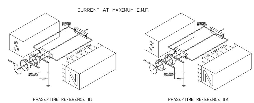
First, we know that we can link single-phase generators to get multiple phases. To do this, we just displace the windings, like we do when we have a three-phase generator and displace the windings by 120?.

The following is a simple generator using a wire loop. There are two places where we achieve maximum EMF and that is when the loop is cutting the flux lines at the maximum rate (i.e., the loop is horizontal). As we rotate through these positions (the peak) the current drops until the loop is vertical (the zero crossing) and then the current starts to move the other way at the contact rings.

180degP1of7.jpg


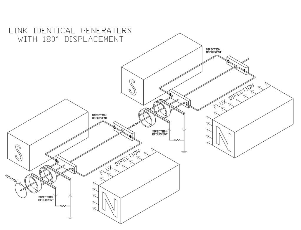
Next, we know that we can take two generators with a phase difference and link them together to get outputs that have a phase difference. The next graphic shows that done and the two generators feeding individual loads.

180degP2of7.jpg


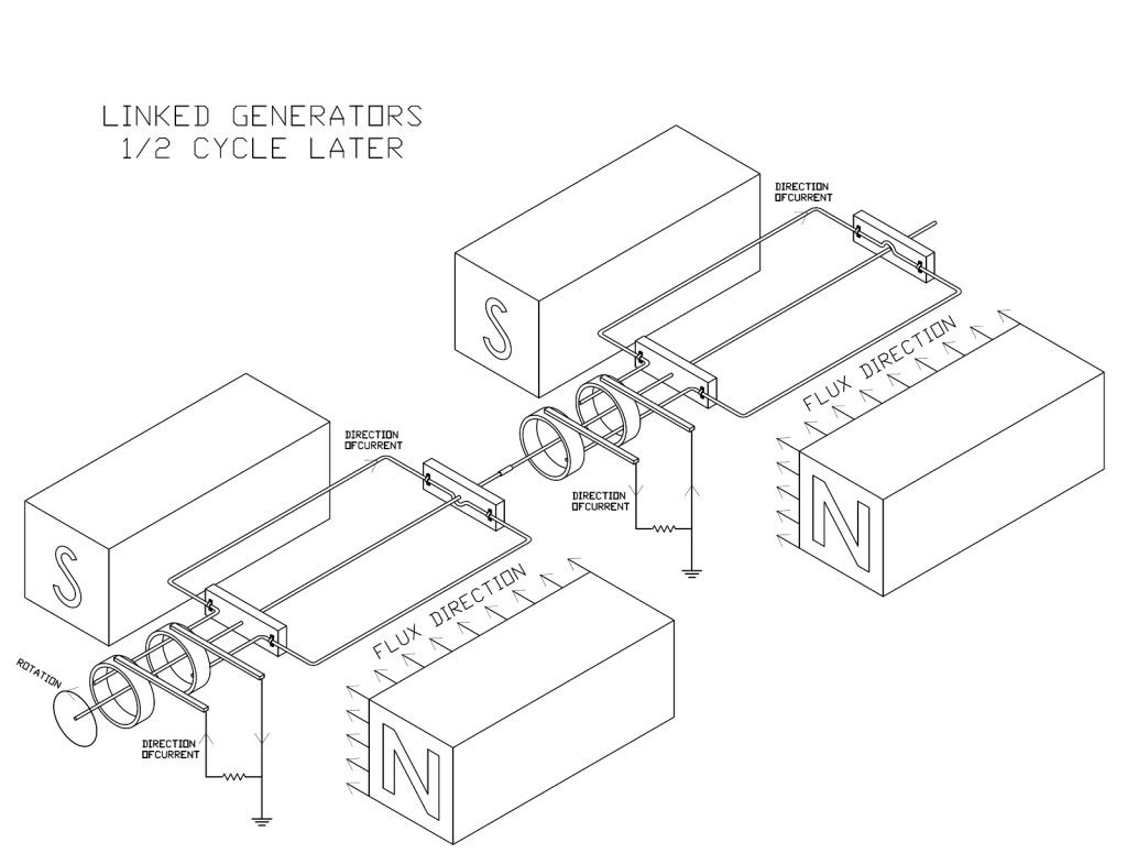
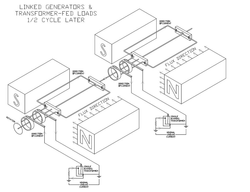
The next graphic shows the same linked setup but at 1/2 cycle later after the current has reversed.

180degP3of7.jpg


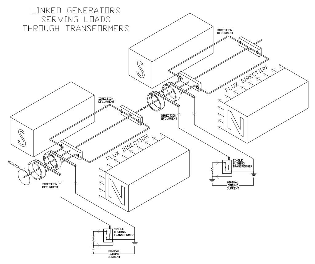
The next graphic shows the linked generators serving loads through transformers. Single-bushing transformers are used so there should be no accusation of "cheating" and moving the terminals as we really only have one physical option available unless we want to cause a ground fault or energize the can. For simplicity's sake, I said ground current was minimal.

180degP4of7.jpg


The next is the same but 1/2 cycle later. Keep in mind that we could have picked either maximum EMF point to be the first one and the choice is completely arbitrary.

180degP5of7.jpg


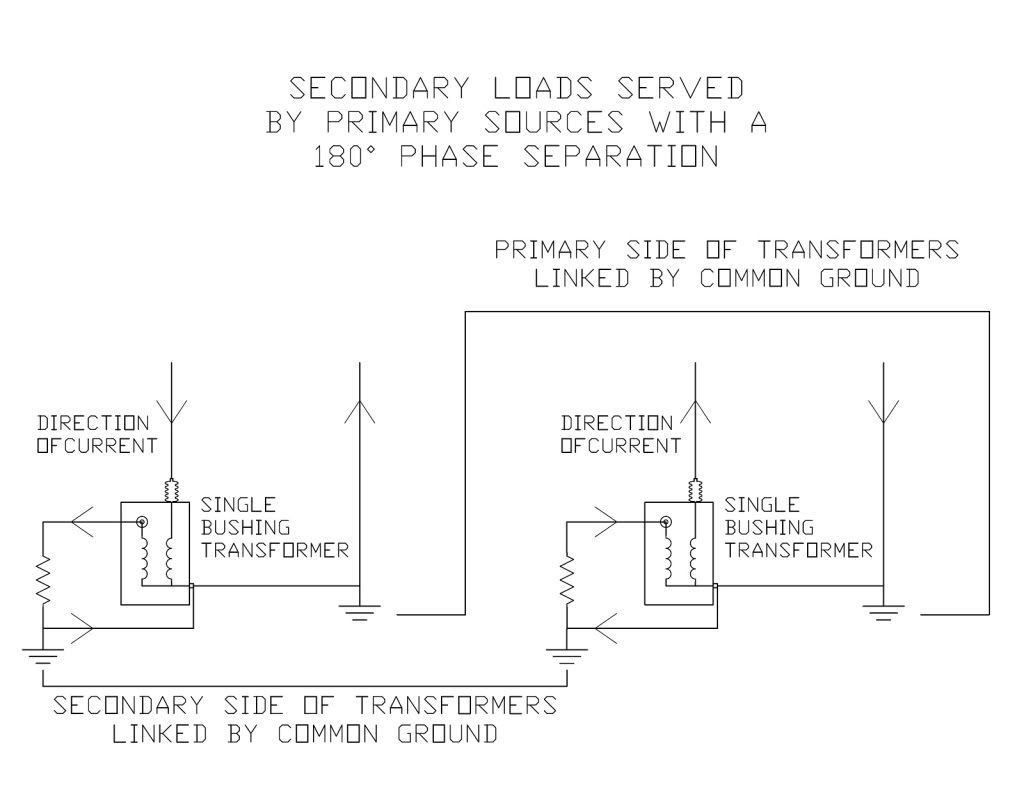
The next graphic is a close-up of the transformers and currents and why the world does not blow up when we link the two phases together. The reason is that these two sources are working in concert: one is pushing while the other is pulling. One has current going towards the loads, the other has current coming from the load. They are mirror images of each other (looking familiar yet?).

180degP6of7.jpg


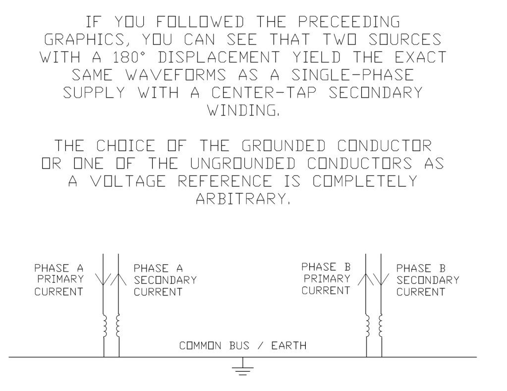
The final graphic shows the summary where we see the eath/neutral as the common bus with the transformers all being tied to the common bus. With a balanced load, the current coming into the bus from one phase is balanced by the current leaving the bus on the other phase and the current only travels on the portion of the bus that joins the two windings (i.e. the portion of the bus that joins the two secondary windings or joins the two primary windings).

With an unbalanced load, the bus will carry unbalanced current all the way from the load back to the portion of the bus that connects the two windings.

The loads could be served with separate bus sections (i.e. a separate neutral for each un-grounded conductor) and that bus would carry the load current all the way back. The beauty of sharing the neutral is that the push-pull happens out on the system instead of at the source and we only have to carry the unbalnce of the push-pull back to the source.

180degP7of7.jpg
 
In my last graphic, the left transformer should have "Phase A primary current" on the left and "Phase A secondary current" on the right instead of secondary on both sides. I'll fix the graphic.
 
In my last graphic, the left transformer should have "Phase A primary current" on the left and "Phase A secondary current" on the right instead of secondary on both sides. I'll fix the graphic.

If you can't edit your posts I can do it for you.
 
Status
Not open for further replies.
Top