705.12

Status
Not open for further replies.
If you had a 100A main breaker in a centerfed panel, fed the lower half of it with 20A from an inverter, and pulled 120A of load on the upper half, why would the main breaker trip?

It would not. That is the big problem with backfeeding centerfed panelboards. In the scenario that all the loads on the interconnected portion diminish to zero, and all the loads on the opposite portion run at as full of power as possible, you exceed the ampacity of the busbar at the point immediately after the main is connected.

A murphy-proofer would say there is no opposite end, while an optimist would say there are two opposite ends for a center fed panel. And for a center fed panel with "semi-main" breakers protecting each half, there are two opposite ends, and a legitimate way to meet 705.12(D) and the 120% rule.
 
Not really. If you look at how the busbar requirements developed over time, the 120% provision used to be allowed in residential applications regardless of where the PV breaker was located. The change to the 120% provision with the end-of-busbar PV breaker was just a means to extend the 120% rule to commercial applications.


You could argue that it makes sense to require engineering supervision in order to apply the 120% allowance to center fed busbar interconnection in commercial and industrial applications. But a residential load profile is very different. Back in the day, you could have added a PV breaker anywhere in a centerfed panel serving a dwelling. Now, you have to spread out the sources of supply, which is perfectly safe in a residential setting.

And that's the point, first we could put the PV breaker anywhere in any residential panel, then we had to put it on the opposite end so as to not feed a load from both sources through the same bus. And we were told that it had to be that way because it was dangerous to do it the old way. Now it's okay to supply a load breaker from two sources through the same bus if it's a center-fed panel. What makes that safe but doing the same with an end fed panel is dangerous? It's contradictory and inconsistent. Either it's okay in a residential panel to feed load breakers from two sources through the same bus or it is not, where the panel bus feeder is connected makes no difference in the question of current through the bus.

I challenge anyone to try to explain why a load breaker in a center-fed panel being fed by both the feeder and PV system is any different than a load breaker in an end-fed panel being fed by both the feeder and PV system. That would be some twisted logic.
 
I challenge anyone to try to explain why a load breaker in a center-fed panel being fed by both the feeder and PV system is any different than a load breaker in an end-fed panel being fed by both the feeder and PV system. That would be some twisted logic.

At an absolute maximum, a pair of branch breakers at the same position would be the full amp rating of the panelboard. If the breakers add up to greater than the panelboard ampacity, they will be at different positions.

In an end-fed panelboard, fed from opposite ends by the PV and main supply, eventually the local current at any given cross section of busbar will diminish to zero, before the source of PV and the source of the main supply accumulate and exceed the busbar ampacity. The current from each opposite fed source flows in opposite directions, and when "added together" it will cancel instead of compound.

If you feed it from ANY position, all the breakers on the side opposite the main supply from it, could in total draw more than the busbar amps, if they add up to more than busbar amps. So allowing main supply + PV to exceed busbar ampacity, only makes sense if they are at opposite ends.
 
Precisely my point.

What you are counting upon when you backfeed centerfed panels at one of the opposite ends, is that the loads are well-distributed between both portions of the busbar, so that it is extremely unlikely that all the top loads are on, while all the bottom loads are off. This is why it requires engineering supervision, to assess the likelihood of it actually being a problem.

One way to help a panelboard in this situation, is to stagger circuits that are built to operate simultaneously across both portions. Like putting your HVAC indoor unit loads on the top, and the corresponding outdoor unit loads on the bottom.
If your calculated load cannot exceed the bus rating, it would never be a problem under nominal conditions.

Here's the typical scenario presented for the problem...


If you have 75A of current going out on the upper left and 40A going out on the upper right, yes you have an overloaded bus... but you have a 15A greater load than permitted under the NEC and a violation in and of itself. Under nominal conditions, you cannot compliantly have more than 100A load connected to the bus. So to talk about bus current over 100A is getting into fault condition scenarios as equipment ratings go. The catch is, if the sum of the supply breakers is 120% of the bus rating as permitted by Code, I find it hard to call 115% current through the bus a fault condition. :slaphead:

Simple solution. Simply limit the sum of source breaker ratings to the bus rating where the sum of the load breaker ratings exceeds the bus rating. If you want to go over, limit the sum of the load breaker ratings to the bus rating. We could even get into whether a load breaker is supplied from the same or opposite directions... :D
 
If you had a 100A main breaker in a centerfed panel, fed the lower half of it with 20A from an inverter, and pulled 120A of load on the upper half, why would the main breaker trip?

Because chances are you'll be pulling the 120A at night or when a cloud passes overhead. That's why I say in order to pull the load when you actually have full inverter output would require a fairly deliberate effort. (Also, btw, it should only be a 116A load.)

Think of it this way:

If the same panel never had the main breaker trip before the inverter was installed, it should never see an overload afterward. If it does, there's also been some other contributing factor added that's probably its own violation (such as a load added without a proper load calc).
 
Last edited:
Because chances are you'll be pulling the 120A at night or when a cloud passes overhead. That's why I say in order to pull the load when you actually have full inverter output would require a fairly deliberate effort. (Also, btw, it should only be a 116A load.)

Think of it this way:

If the same panel never had the main breaker trip before the inverter was installed, it should never see an overload afterward. If it does, there's also been some other contributing factor added that's probably its own violation (such as a load added without a proper load calc).
Of course I know all that (not my first rodeo), but if you have a standard panel with the main breaker at one end of the bus and the backfed breaker at the other, there's nothing that anyone can do after you have left short of moving your supply breakers or adding more of them that can result in a bus overload. The same is not true of a center fed panel.

What's the point of a center fed panel, anyway?

The point of a centerfed panel is to reduce busbar ampacity, so that only about half of the current flows to each group of breakers on both sides of the main supply.

IMO, I don't see much of a purpose to a centerfed panelboard, when your equipment is small enough to classify as a panelboard or load center. I see more of a purpose in switchboard/switchgear/Motor Control Center applications, where the busbar is thousands of amperes, and you are strategically arranging the loads and sources so that it only needs to be half as large as the main supply. Customization is more common in these applications, since even a default configuration is a custom product.
 
Of course I know all that (not my first rodeo), but if you have a standard panel with the main breaker at one end of the bus and the backfed breaker at the other, there's nothing that anyone can do after you have left short of moving your supply breakers or adding more of them that can result in a bus overload. The same is not true of a center fed panel.

Yes, well, as Solar Pro pointed out, the argument over whether the opposite-end rule is really necessary for residential installations applies to all panels, not just centerfed. The new 2017 rules basically amount to 'we require you to make it as safe as possible without requiring a panel replacement in common situations.' I can get behind that. In either case someone could move stuff around and make it somewhat less safe, but that would be on them.

What's the point of a center fed panel, anyway?

In vertically divided residential meter/main combos, I presume it's simply to save busbar material and increase wiring space on the meter side. The bottom lugs of the meter are in the middle of the vertical space, so it made sense to just bring the busbars directly over. Before solar was common it was a good design from the manufacurers pointnof view and didn't have a negative impacton anyone else.
 
What's the point of a center fed panel, anyway?

The point is that there a lot of center-fed panels in the field, especially in California. In jurisdictions some where center-fed panels are common, installers routinely incur a $1,000 tax to install a PV system simply because AHJs require a service upgrade to replace the existing panel. These upgrades don't improve safety in practice; they just drive up costs. If you've ever looked at a residential load profile in real time, perhaps via a circuit-level interface like Curb, it's pretty clear why you can add 20 A of PV to either end of a 100 A center-fed panel busbar: the continuous loads at a dwelling rarely if ever approach the maximum bus rating. It would be hard for me to max out my panel at home, and we have real HVAC loads in Texas; it's easy to draw it on paper, but that doesn't describe anything that you would ever see in a residential setting.
 
While you roll this one around in your mind remember that there is no code requirement that dictates the placement of load breakers in a panel other than to balance phases, center-fed or otherwise. Someone could put all the load breakers on one side of the bus in a center-fed panel and then put the PV breaker at the end of the bus on the other side and comply with the NEC. All the loads breakers would be fed by two sources from the same side. This is equivalent to an end-fed panel with the PV breaker right next to the main breaker.

Why is this acceptable for a center-fed panel and not an end-fed panel? There really is no rational reason.
 
It used to be perfectly acceptable in residential applications. Get out your vintage Code editions and check. You could load the busbar at 120% regardless of breaker placement in dwellings. None of those pre-NEC 2008 systems has caused a problem, not even the center-fed panels.

We all know that there are safety factors built into the Code and the product safety standards. Loading a busbar at 120% is probably equivalent to loading it at its max safe design load. Just saying.
 
Also, what's the busbar overload failure more?

It's not like the copper/aluminum busbar is going to melt at 120% loading, not even close. Worst case scenario seems like nuisance tripping. Excess heat inside the panel temperature-sensitive OCPDs trip sooner than they are supposed to.

Granted, I'm not an engineer, but that sounds like a failsafe failure mode to me.

If I were losing consulting fees due to the Code change, maybe I'd be more alarmed.


That's the consequence of having 120% distributed loading throughout the breakers in the panelboard, which is the issue in opposite-end fed panelboards. I agree, that is a failsafe method, provided that thermal methods are part of the breakers' tripping mechanism. A breaker with pure magnetism as its tripping method, would not trip on overheating. And that is more of a theoretical breaker than a practical one.

With center-fed panelboards, fed with PV on one side, there is the added failure mode of the local current on the busbar itself, exceeding the busbar rating. This is not a fail-safe failure mode. It is true that like all engineered products, it is built with safety factors. Thus 120%, or possibly even 150%, of the nominal amps on the busbar may not cause noticeable failure. But that is not the kind of thinking to have when assessing whether or not a product is safe. No installation should be built with the possibility of cheating the design margins by operating at greater than the allowable usage, just because the allowable usage is less than the ultimate usage at failure.
 
Right. We should build system to meet the Code, because the stakeholders on the Code-Making Panel have determined that doing so is safe. The Code says that you can apply the 120% rule to a center-fed panel when the PV breaker is at either end of the busbar.

As far as what the actual safe limits are of busbar overloading from a parallel power production source, my assumption is that the push in recent Code cycles for a 150% allowance (in lieu of 120%) is based on actual laboratory testing, which is manufacturers can justify now based on the increasing volume of fielded systems.
 
Last edited:
Right. We should build system to meet the Code, because the stakeholders on the Code-Making Panel have determined that doing so is safe. The Code says that you can apply the 120% rule to a center-fed panel when the PV breaker is at either end of the busbar.

As far as what the actual safe limits are of busbar overloading from a parallel power production source, my assumption is that the push in recent Code cycles for a 150% allowance (in lieu of 120%) is based on actual laboratory testing, which is manufacturers can justify now based on the increasing volume of fielded systems.

The 2014 NEC does not say that you can apply the rule to a center-fed panel and requires engineering supervision to do anything that involves multiple sources feeding a centerfed panel or a multiampacity busbar.

The 2017 NEC now allows you to use one side, but not both sides, of a center-fed panelboard in dwellings. The blindspot is that it doesn't specify what to do for commercial and industrial applications, possibly where it is a switchboard instead of a panelboard.

It applies in both cases. The Code Making Panel has amended NEC 2014 to match NEC 2017. See TIA 1234.
 
I did some digging into the code making that went into the changes for the 120% rule in the 2008 NEC. It seems that initially the goal was to have 200% but they scaled it back to 120% with the intention that testing would be performed to determine if 200% would be a reasonable value. As far as I can tell this testing has not occurred, or if it was I have not found any results published.

Here was the TCC's proposed wording which would have allowed 200%:

690.64(C)(7) Bus or Conductor Rating. Unless the panelboard is rated not less than the sum of the ampere ratings of all overcurrent devices supplying it, a connection in a panelboard shall be positioned at the opposite (load) end from the input feeder location or main circuit location. A permanent warning label shall be applied to the distribution equipment with the following or equivalent wording:
WARNING
PHOTOVOLTAIC SYSTEM SOURCE OUTPUT
DO NOT RELOCATE THIS OVERCURRENT DEVICE

Here is the substantiation the TCC provided for the change. The highlights are mine.


Although the Technical Correlating Committee requested that CMP-9 comment on Proposal 13-61, and by this comment the panel has done so, the technical issues raised in that and in the associated proposals apply to all systems capable of interconnection and parallel operation using multiple sources. For this reason, CMP-9 believes that the CMP-13 actions in Articles 690, 692, and 705 must be correlated in this respect, and is providing comments to the comparable proposals and panel actions in all of these articles. In addition, the layout and content of this comment reflect a consistency of approach that assures correlation with the corresponding language in Articles 692 and 705.

CMP-9 agrees that it is possible to assure that the busbars of panelboards receiving supply current from two sources can be arranged so the busbars will not exceed their ampacity (the “opposite end” scenario accepted under this proposal), however, CMP-9 points out that such an arrangement allows for up to double the amount of load to be taken from the panel for indefinite periods of time. Current product standards do not anticipate the effect of I2R heating losses under these conditions, which could severely impact the performance of essential components within the distribution equipment. Before the NEC recognizes this type of connection, it is essential that careful testing be carried out to determine the acceptable parameters that should be applied in these cases.
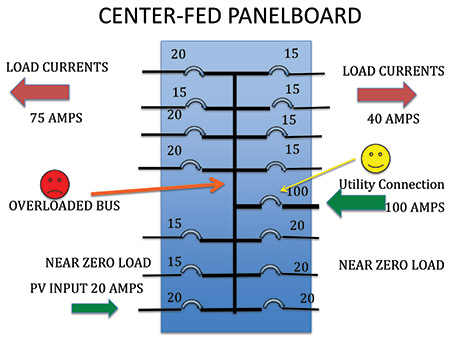
For example, if a large PV system provides 100 amperes of power to a panel in an interactive system rated 100 amperes, and this panel is supplied by a normal utility supply of 100 amperes, the branch circuit and feeder loads supplied by this panel could total 200 amperes. Although such a load should not exist due to required sizing rules relative to Article 220 calculations, the requirement for individual protection for panelboards (now set to apply to all panelboards by virtue of CMP-9 action in this cycle) anticipates that these load calculations are easily circumvented given the relative ease of circuit modifications.

CMP-9 is suggesting revisions to the backfeed allowance that more closely track the actual provision in Article 408 that is intended to be varied in this Chapter 6 article. Our wording also omits the deadfront clamping language in the proposal because such construction is clearly required by the product standard and pointless here; furthermore, the deadfront does not actually “clamp all circuit breakers to the panelboard busbars.” In addition, we are offering a different version of the fine print note to address concerns raised in the voting. CMP-9 understands that CMP-13 was using the term (identified) in its Article 100 sense and not in the sense of a marking, however, this wording avoids any confusion. Other changes are editorial and in the interest of correlation, where technically appropriate, with other interactive articles.

CMP-9 expresses its willingness to assign a task group to work with CMP-13 and other industry parties to provide a carefully substantiated global approach to double-fed distribution equipment applied in interactive settings for the 2011 NEC. This might include specially targeted allowances for equipment listings that would cover such interconnections. In the mean time, this comment does broaden the 120 percent allowance from dwellings to all occupancies. Because of the I2R relationship, an allowance for an an additional 20% loading (one fifth) would only increase the heating losses by 4% (one twenty fifth), which should be tolerated by existing equipment designs even if the interconnection does not occur at the opposite end of the bus from the normal supply. This comment incorporates the opposite-end rule from the CMP-13 action on this proposal as a trade-off for the occupancy expansion, thereby ensuring that an overloaded busbar does not exacerbate the heating problem.

Other comments questioned this 4% heating loss calculation:

The PV Industry Forum requests clarification and confirmation of the CMP 9 calculation of a 4% possible added heating due a potential 120% increase in load currents. Other calculations indicate that the potential heating may be as high as 44%. Other panel board manufacturers have indicated that the overheating is not an issue as long as the panel is fed at opposite ends.


I'm sure there were related discussions that took place at meetings that were not recorded but this probably gets the grist of what was driving the change from the 2005 to the 2008 NEC. There was a push for 200%, but with no testing to back it up they settled to maintain the 120%. The addition of the requirement to place the PV CB at the opposite end was a compromise to extend the applicability from residential to all panels. Supposedly testing was going to provide better guidance for the 2011 code changes but it does not seem to have been done.
 
In case anyone is interested here is the record of the substantiation for the 120% rule from way back in 1987. Remember that the 1984 NEC had nothing about interconnection in 690 in the final code.

In the 1987 NEC the 120% rule was put in and this was the substantiation for adding 690.64(2) with the 120% exception.

The exception will permit connection to an existing dwelling service panelboard without requiring a decrease in the rating of the main service disconnecting means. The 120 percent factor, is based upon generally accepted diversity in dwelling occupancy services. As an example, Note 3 to Table 310-16 recognizes this for dwelling occupancy service-entrance conductors.​


So my reading of this is that while the allowance would make it possible for the panel to be loaded to 120% they assumed that in a residential usage it would not happen. Just as note 3 to the conductor sizing table allowed reduced size conductors for residential services, a #4 for a 100A service for instance, the assumption was that a residential service would not actually draw the full service rating at one time much less 120% of it. No one was worried about bus current loading, or someone putting 120A of load on a 100A service. If even 100% loading were a problem the service entrance conductors would be burning up all over the place long before PV was being interconnected. People have thought up a problem that so far has not been shown to exist in the real world.

Unfortunately this has been something that has plagued PV for decades, people think up a worst case situation and feel they need to prevent it from ever happening even though the rest of the code is based on dealing with real world usage and not the worst case that can be imagined. We get the short end of the stick because PV is new and with no prior experience the imagination is free to fly.
 
Status
Not open for further replies.
Top