Ansul System

Status
Not open for further replies.
I'm going to do a site check to see actually see what they have. It's hard for me to know for sure just by a description over the phone.

But from what I was told, it's going to be a little more difficult wiring this since the equipment has already been direct wired, not taking the Ansul system into account when the equipment was wired. Also from their description, they only have an electric 3? piece of equipment under the hood, not gas. Also, a makeup air fan and exhaust.

So just guessing from the description, I think the way I will do it is use one micro switch to control the fans. Maybe like this:

hot to N/O contact on the micro switch
hot to supply side of fan switch (hoping 1 switch for exh, and make up)
from load side of switch to common of micro switch and exh. fan
from N/C contact on micro switch to make up fan

Then a second micro switch for the 3-pole contactor.
Like this:

hot to common on 2nd micro switch
N/C contact on micro switch to coil on contactor

Like I said, the difficult part will be redirecting the wiring since its already wired.
I suppose I need to set a junction/pull box. Then mount the 3-pole contactor and run a conduit to the control head for the wiring at the micro switches. Then redirect the wiring from the equipment into/out of the junction box.

Does this sound right or the best way to do this, providing the facts given me are correct?
If there is a central fire alarm system, I'll bet you'll need to connect to that too.
 
I'm going to do a site check to see actually see what they have. It's hard for me to know for sure just by a description over the phone.

But from what I was told, it's going to be a little more difficult wiring this since the equipment has already been direct wired, not taking the Ansul system into account when the equipment was wired. Also from their description, they only have an electric 3? piece of equipment under the hood, not gas. Also, a makeup air fan and exhaust.

So just guessing from the description, I think the way I will do it is use one micro switch to control the fans. Maybe like this:

hot to N/O contact on the micro switch
hot to supply side of fan switch (hoping 1 switch for exh, and make up)
from load side of switch to common of micro switch and exh. fan
from N/C contact on micro switch to make up fan

Then a second micro switch for the 3-pole contactor.
Like this:

hot to common on 2nd micro switch
N/C contact on micro switch to coil on contactor

Like I said, the difficult part will be redirecting the wiring since its already wired.
I suppose I need to set a junction/pull box. Then mount the 3-pole contactor and run a conduit to the control head for the wiring at the micro switches. Then redirect the wiring from the equipment into/out of the junction box.

Does this sound right or the best way to do this, providing the facts given me are correct?

That's where it might be easier to just pull out the existing breaker and replace it with a shunt trip breaker, either way it is legal. Keep in mind though a three pole shunt trip usually uses four pole spaces.
 
That's where it might be easier to just pull out the existing breaker and replace it with a shunt trip breaker, either way it is legal. Keep in mind though a three pole shunt trip usually uses four pole spaces.

You can also use a shunt trip or contactor to control a feeder for a panel that has everything that needs to be shut down supplied from that panel.
 
You can also use a shunt trip or contactor to control a feeder for a panel that has everything that needs to be shut down supplied from that panel.

If one was to go this route I think you would need to not feed the constant hot to the Ansul micro switch and the exhaust fan from the new sub panel. Also, you would need to make sure the exhaust fan would be on regardless of the position of the switch that controls it.
 
If one was to go this route I think you would need to not feed the constant hot to the Ansul micro switch and the exhaust fan from the new sub panel. Also, you would need to make sure the exhaust fan would be on regardless of the position of the switch that controls it.

Exhaust fan is not an item that gets shut down when the fire suppression is activated so it can not be in the controlled panel.

If you need to ensure the fan is on before cooking appliances will run then the contactor is easier to do than the shunt trip same control voltage can run two contactors - one for the fan and one for the feed to appliances. Can even interlock the appliances through an aux contact on the fan.
 
I havent always totally agreed with leaving the exhaust fan running.

To me wether your pushing air with a supply fan or sucking air with an exhaust fan, your still moving air.
 
The logic behind it is to remove the possible deadly smoke from the room.

And there is never any grease in the hood or the exhaust duct, NOT. With grease fire within exhaust ducting, turning fan off allows heat to build up and increase the risk of spreading that fire, but pulling air through it makes it not much different than many combustion units where the heated air is fed directly through the burner.
 
The arm-chair theorizing about turning the exhaust fan off is exactly why I so bluntly said: READ the standard.

One is likely to be surprised at the standards' position on the issue.
 
And there is never any grease in the hood or the exhaust duct, NOT. With grease fire within exhaust ducting, turning fan off allows heat to build up and increase the risk of spreading that fire, but pulling air through it makes it not much different than many combustion units where the heated air is fed directly through the burner.

I've never heard it explained that way, Thanks.
 
I've never heard it explained that way, Thanks.

I don't know if that is recognized by any codes or any AHJ but sure seems logical to me.

You ever been troubleshooting a burner and have it light for any reason without designed air flow over it, the combustion chamber and any associated ducting get hot pretty fast.
 
It makes sense that if you are directing the heat up and out that is is somewhat of a controlled catastrophe.
Whereas if the fire was stuck in the middle of the exhaust duct I could see where it would quickly melt down and find its way out.
Even if its not recognized, thats the best explanation I've heard in a long time.
 
I did the site check today and it doesn't look like it's going to be quite as difficult as I thought. I thought they had the equipment wired but they just brought the wiring to the area. The only thing that is wired is the exhaust fan, light, and make up air/fan.

Since that is all the equipment that is there, I think just mounting a pull/junction box big enough to handle the contactor and all the wiring will suffice.

I plan to:
run 3 wires from the control head/micro switch
run the wires from the switch for the fans
run the wires from each fan
All into the box and make all connections there.
This is if, you're allowed to use just one micro switch for all the control.

See any problem with this?

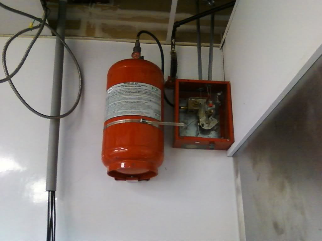
Here is a pic of the system. The conduit to the left contains the wires for the appliance. It would be easy to drop them right into the junction box containing the contactor.

AnsulSystem2012-10-23001.jpg
 
Not to be Picky...

Not to be Picky...

This is actually an Amerex system, but most everything we've said still applies.
 
And there is never any grease in the hood or the exhaust duct, NOT. With grease fire within exhaust ducting, turning fan off allows heat to build up and increase the risk of spreading that fire, but pulling air through it makes it not much different than many combustion units where the heated air is fed directly through the burner.

Also with the fan running, some of the retardent will be draw up into the duct, helping extinguish the said grease that is burning.
 
Also with the fan running, some of the retardent will be draw up into the duct, helping extinguish the said grease that is burning.

The only so "said" grease is in a brand new system with less than ~ 100 hours. All others have some grease in them and so does all the cooking appliances under the hood. Ever had to service a commercial fryer? If it still is under warranty it may not have much build up in it, but they seldom fail during that time. I swear all others have wiring compartment completely filled with a gel like substance that was not there when it was new, and it doesn't want to come out either.:happyyes:
 
This is actually an Amerex system, but most everything we've said still applies.

Kleenex
Vise Grips
Channel Locks
Romex
Coke :p:)

Well I'm new to any dealings with the fire suppression systems, but all I ever hear people call them is "Ansul"

The rep of the company is supposed to bring a micro switch for this system. I've never seen one. Anyone got a link to an image of the switch?
 
Status
Not open for further replies.
Top