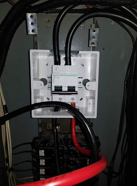
Circuit Breaker teardown and defective Siemens latching mechanism

Merry Christmas
Status
Not open for further replies.

tersh

Senior Member
Location
new york
I know 1 AWG will work with the Siemens Lugs. But it has a bottom with strip (shown at left)). I need something flat like in the right one (but the right one is china made without any brand, not UL listed and the bottom is not so flat). I just need a branded chair lugs that can accept 1 AWG with flat bottom. Any idea? What brands do you or other electricians/engineers use when such quality chair lugs are required?


It came to my attention that my electrician was in possession of 5 very inferior lugs where there are only few contacts points between the surface of it and the bus bar. So let me take the opportunity to thoroughly understand its behavior. Supposed the bus bar and lugs have few contact points only like the following:

Kspf5A.jpg

Consider the red bits as only 0.5 millimeter contact points between bus bar and chair lugs where there are only ver few. At a small amperage, the few contact points would heat up. Let's say it crosses certain ampere and heating threshold where the contact points are on the merge of melting. Would it just melt? If it does, would the bus bar and chair lugs reposition themselves so there is more even contacts? (assuming the chair lugs goes down by gravity). Or would arc form between the gap and destroying other parts of the surface?

I couldn't find details of this in google and I've wanted to understand the details lately. So what happens in joule heating and melting (and arcing?) in microscopic contact points between bus bar and chair lugs when the surfaces are not evenly in contact? What's the step by step progression when they get destroyed (or is there readjustment to equilibrium where there is eventually more contacts as they melt into each other surface)?
 

mbrooke

Batteries Included
Location
United States
Occupation
Technician
I know 1 AWG will work with the Siemens Lugs. But it has a bottom with strip (shown at left)). I need something flat like in the right one (but the right one is china made without any brand, not UL listed and the bottom is not so flat). I just need a branded chair lugs that can accept 1 AWG with flat bottom. Any idea? What brands do you or other electricians/engineers use when such quality chair lugs are required?

qyPEI0.jpg


Blackburn is one Burndy is another.


Personally I would start a new thread and ask what others/ most preferred are, this will give you more replies.
 

tersh

Senior Member
Location
new york
Blackburn is one Burndy is another.


Personally I would start a new thread and ask what others/ most preferred are, this will give you more replies.

That's all I need to know. I don't want to start new thread on it because it may sound like DIY which the moderators can lock. I don't want to explain I took up engineering long ago and have electricians to do it because it would sound complicated.

Anyway I have gotten every information now so the electrician can start to migrate from the old plug in panel to din rail breakers due to 1-pole breakers put in a 2-pole system where only 1 of the 2 pole can really trip. But it would take time to install them as the electrician has to do it very carefully and we have to time power shutdown at a time so the elderly occupants won't be hassled, lol.

Thanks for all the information about breakers (esp din rail versions) and stuff.
 

kwired

Electron manager
Location
NE Nebraska
It came to my attention that my electrician was in possession of 5 very inferior lugs where there are only few contacts points between the surface of it and the bus bar. So let me take the opportunity to thoroughly understand its behavior. Supposed the bus bar and lugs have few contact points only like the following:

Kspf5A.jpg

Consider the red bits as only 0.5 millimeter contact points between bus bar and chair lugs where there are only ver few. At a small amperage, the few contact points would heat up. Let's say it crosses certain ampere and heating threshold where the contact points are on the merge of melting. Would it just melt? If it does, would the bus bar and chair lugs reposition themselves so there is more even contacts? (assuming the chair lugs goes down by gravity). Or would arc form between the gap and destroying other parts of the surface?

I couldn't find details of this in google and I've wanted to understand the details lately. So what happens in joule heating and melting (and arcing?) in microscopic contact points between bus bar and chair lugs when the surfaces are not evenly in contact? What's the step by step progression when they get destroyed (or is there readjustment to equilibrium where there is eventually more contacts as they melt into each other surface)?
If those contact areas "burn or melt" and that ends up making less overall contact pressure, you have lots of resistance issues in development.
 

kwired

Electron manager
Location
NE Nebraska
I know 1 AWG will work with the Siemens Lugs. But it has a bottom with strip (shown at left)). I need something flat like in the right one (but the right one is china made without any brand, not UL listed and the bottom is not so flat). I just need a branded chair lugs that can accept 1 AWG with flat bottom. Any idea? What brands do you or other electricians/engineers use when such quality chair lugs are required?

qyPEI0.jpg
Left lug is a common OEM product design that lug hangs past end of the bus it was intended to attach to, and that ridge on the back is to prevent it from wanting to turn around the mounting bolt as you tighten the set screw for securing the installed conductor. Very common to see design like that as the main lugs in a main lugs only panel.
 

romex jockey

Senior Member
Location
Vermont
Occupation
electrician
QUOTE=tersh;1978176]
It came to my attention that my electrician was in possession of 5 very inferior lugs where there are only few contacts points between the surface of it and the bus bar. So let me take the opportunity to thoroughly understand its behavior.

Now i wonder if i could be one of those 'electricians'.....

I couldn't find details of this in google and I've wanted to understand the details lately. So what happens in joule heating and melting (and arcing?) in microscopic contact points between bus bar and chair lugs when the surfaces are not evenly in contact? What's the step by step progression when they get destroyed (or is there readjustment to equilibrium where there is eventually more contacts as they melt into each other surface)?

I'm curious as to the details as well , perhaps there are NRTL studies promoting listing requirements ?

~RJ~
 

tersh

Senior Member
Location
new york
mbrooke, I would like to hear you experiences and knowledge about this.. and others who know.

The local electrical engineer and electrician said there may not be problems with inserting two wires in a single breaker lug. See:

phfFbz.jpg


They said it's more stable than using a red wire nut tying up 3 AWG 10 to each terminal lug using pigtail (which they actualy did too with red wire nut but resulting in mess of wire). Now my question is not whether this wire nut would work (they had done it but resulting in unneat wies). But theoretical reasoning why two wire lugs inside a single breaker terminal could be problematic.

Given a 30A breaker and AWG 10 wires. What is the problem if you insert 2 pcs of AWG 10 to each terminal (hence 4 wires for each breaker like above test setup)? I'm not asking about current and protection by breaker or capacity as I have taken all these into account already (and the local EE too and the electrician), But I'm just asking what is technically wrong with inserting 2 wires in each terminal (when the breaker doesn't have any listing about it). Remember as long as the terminal is screwed tight and no loose wire, there would be full electrical contacts between them and no arcing, heating, right? What can possibly go wrong?

Please share pictures of breaker terminal lug that can accept one wire and two wires. I'd like to see the difference between them. Thanks!
 

kwired

Electron manager
Location
NE Nebraska
mbrooke, I would like to hear you experiences and knowledge about this.. and others who know.

The local electrical engineer and electrician said there may not be problems with inserting two wires in a single breaker lug. See:

phfFbz.jpg


They said it's more stable than using a red wire nut tying up 3 AWG 10 to each terminal lug using pigtail (which they actualy did too with red wire nut but resulting in mess of wire). Now my question is not whether this wire nut would work (they had done it but resulting in unneat wies). But theoretical reasoning why two wire lugs inside a single breaker terminal could be problematic.

Given a 30A breaker and AWG 10 wires. What is the problem if you insert 2 pcs of AWG 10 to each terminal (hence 4 wires for each breaker like above test setup)? I'm not asking about current and protection by breaker or capacity as I have taken all these into account already (and the local EE too and the electrician), But I'm just asking what is technically wrong with inserting 2 wires in each terminal (when the breaker doesn't have any listing about it). Remember as long as the terminal is screwed tight and no loose wire, there would be full electrical contacts between them and no arcing, heating, right? What can possibly go wrong?

Please share pictures of breaker terminal lug that can accept one wire and two wires. I'd like to see the difference between them. Thanks!
There may not be any problems with multiple conductors in such lugs, but most of what we run into are not listed/identified to accept multiple conductors, so per NEC we can't put more than one in them in that situation.

Where you start to commonly see lugs intended to accpt multiple conductors is once you get into 400 amp frame size equipment or larger. I think it is common to use such lugs partly because that size and larger is more common to see parallel conductors.

Lug on this page is somewhat typical of what you might see that will accept one large conductor or two smaller conductors (typically for parallel applications) notice how the hole the conductor(s) are inserted into are not "round" but rather oblonged. They aren't always exactly like this one but oblong shape in some way to that hole is pretty common.
http://www.nsiindustries.com/catalo.../mechanical-copper-and-dual-rated-lugs/bs400t
 

mbrooke

Batteries Included
Location
United States
Occupation
Technician
mbrooke, I would like to hear you experiences and knowledge about this.. and others who know.

The local electrical engineer and electrician said there may not be problems with inserting two wires in a single breaker lug. See:

phfFbz.jpg


They said it's more stable than using a red wire nut tying up 3 AWG 10 to each terminal lug using pigtail (which they actualy did too with red wire nut but resulting in mess of wire). Now my question is not whether this wire nut would work (they had done it but resulting in unneat wies). But theoretical reasoning why two wire lugs inside a single breaker terminal could be problematic.

Given a 30A breaker and AWG 10 wires. What is the problem if you insert 2 pcs of AWG 10 to each terminal (hence 4 wires for each breaker like above test setup)? I'm not asking about current and protection by breaker or capacity as I have taken all these into account already (and the local EE too and the electrician), But I'm just asking what is technically wrong with inserting 2 wires in each terminal (when the breaker doesn't have any listing about it). Remember as long as the terminal is screwed tight and no loose wire, there would be full electrical contacts between them and no arcing, heating, right? What can possibly go wrong?

Please share pictures of breaker terminal lug that can accept one wire and two wires. I'd like to see the difference between them. Thanks!


Square D QO and Homeline 15-30 amp breakers can take 2 wires of the same size.


While your breaker setup above is an NEC violation, I doubt its actually dangerous as long as both wires are copper or both aluminum at the same time. Ie, do not mix metals. I've TONS of double tapped breakers in residential without issue.
 

tersh

Senior Member
Location
new york
Square D QO and Homeline 15-30 amp breakers can take 2 wires of the same size.

Is it stated in the breaker itself that it can take 2 conductors? Where are such written?

While your breaker setup above is an NEC violation, I doubt its actually dangerous as long as both wires are copper or both aluminum at the same time. Ie, do not mix metals. I've TONS of double tapped breakers in residential without issue.

Also they must be same size. If one is larger or smaller, the smaller one can slip.

You have seen tons of double tapped breakers in residential? Don't they have annual inspections?
 

tersh

Senior Member
Location
new york
mbrooke, Late last year we were discussing about cable leakages and appliance leakages of current which you said was the reason why European RCD uses 30mA tripping threshold instead of 5mA.

Since my 5mA GFCI protection is really whole house now (100% protection even the lights) spread into 6 GFCI breakers in main panel. I'd like to know something about the dielectric leakages of current. if the dielectric insulation in cable or appliance is not good. Where will the current leak to? Is it more apparent when there are EGC or GEC installed, like in Europe? But without any EGC or even GEC. Where will the current leak to?

So far no nuisance tripping yet for my whole house GFCI protection. I'm thinking where cable leakages and appliance leakages can occur. Did you mean like the water pump put on concrete floor, but if it is insulated from the floor, how will the current leak?
 

kwired

Electron manager
Location
NE Nebraska
Is it stated in the breaker itself that it can take 2 conductors? Where are such written?


Also they must be same size. If one is larger or smaller, the smaller one can slip.
Last sentence in 110.14(A): Terminals for more than one conductor and terminals used to connect aluminum shall be so identified.

No rule stating where it must be written, but is usually on the breaker, lug, etc. somewhere. If it says something like 14-2 AWG that typically means one conductor in the size range mentioned. If it says (1) 600 MCM-4 AWG (2) 250 MCM-1/0 AWG that means one conductor between 600MCM and 4 AWG or two conductors (same size and type) between 250 MCM and 1/0 AWG.

You have seen tons of double tapped breakers in residential? Don't they have annual inspections?
That there is funny:lol::lol:
 

tersh

Senior Member
Location
new york
Last sentence in 110.14(A): Terminals for more than one conductor and terminals used to connect aluminum shall be so identified.

No rule stating where it must be written, but is usually on the breaker, lug, etc. somewhere. If it says something like 14-2 AWG that typically means one conductor in the size range mentioned. If it says (1) 600 MCM-4 AWG (2) 250 MCM-1/0 AWG that means one conductor between 600MCM and 4 AWG or two conductors (same size and type) between 250 MCM and 1/0 AWG.

That there is funny:lol::lol:

kwired. In your expert opinion. How many times do you think you can bend up and bend down the same portion of the wire for say AWG 3 and AWG 2 or in between before they suffer microscopic breaks in the cooper metal?
 

tersh

Senior Member
Location
new york
How do you come up with these questions???

-Hal

I didn't just think up the questions. All my questions were due to actual applications issues:

3pqfvs.jpg


The electrician is migrating the panel from plug in to din rail and he bends the wires up and down. So I wonder how many times it can happen before micro cracks in the cooper can occur. I was not asking about the radius which we know but trying to bend with minimum radius up or down (or in opposite directions). If he does it 10 times, the wire can fracture. It's 30mm^2 or exactly between AWG 3 and AWG 2. But I wonder if less than 5 times, how would the wires behave.
 

tersh

Senior Member
Location
new york
Why don't you let your "electrician" worry about it?

-Hal

Since it's not his. He doesn't care. He bends the wires in different positions up and down left and right with multiple bending at opposite direction. I'm afraid there may be microcracks hence asking how many they can actually be bend back and forth. 30mm^2 is exactly between AWG 3 and 2.
 

mbrooke

Batteries Included
Location
United States
Occupation
Technician
mbrooke, Late last year we were discussing about cable leakages and appliance leakages of current which you said was the reason why European RCD uses 30mA tripping threshold instead of 5mA.

Since my 5mA GFCI protection is really whole house now (100% protection even the lights) spread into 6 GFCI breakers in main panel. I'd like to know something about the dielectric leakages of current. if the dielectric insulation in cable or appliance is not good. Where will the current leak to? Is it more apparent when there are EGC or GEC installed, like in Europe? But without any EGC or even GEC. Where will the current leak to?

So far no nuisance tripping yet for my whole house GFCI protection. I'm thinking where cable leakages and appliance leakages can occur. Did you mean like the water pump put on concrete floor, but if it is insulated from the floor, how will the current leak?

Through a person and to ground.
 

tersh

Senior Member
Location
new york
Through a person and to ground.

I see. This explains why a 5mA GFCI can protect an entire house without leakages because all the devices were isolated. Should there be EGC or GEC. Then it can nuisance trip on dielectric insulation decay and current leakages to the EGC or GEC.

I know EGC is important so in the event of ground fault, it should trip the regular breaker immediately without waiting for a person and a ground via GFCI, which is only used for backup in the US.

But if the appliances have GEC. It should trip the GFCI as well so GEC should be at least a minimum. Hence will assign local electrical engineers for possible GEC installation and breaking concrete in the parking area next time.
 
Status
Not open for further replies.
Top