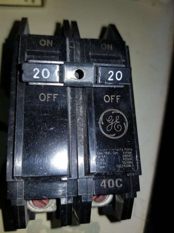
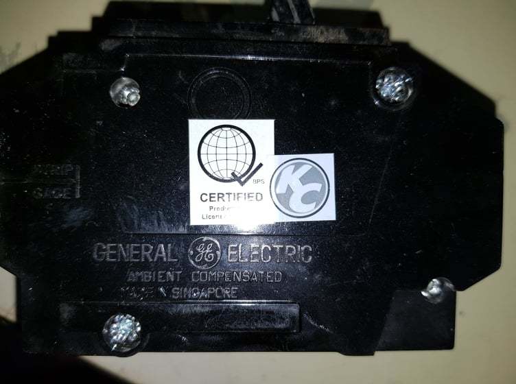
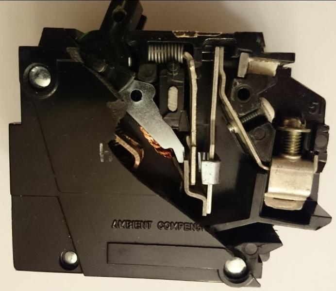
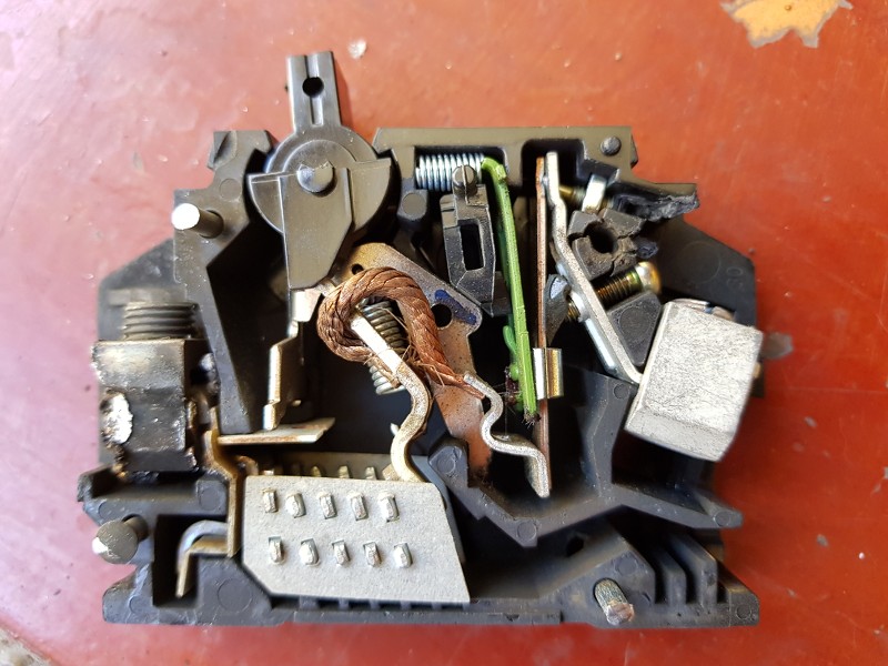
Circuit Breaker teardown and defective Siemens latching mechanism

Merry Christmas
Status
Not open for further replies.

kwired

Electron manager
Location
NE Nebraska
kwired. In your expert opinion. How many times do you think you can bend up and bend down the same portion of the wire for say AWG 3 and AWG 2 or in between before they suffer microscopic breaks in the cooper metal?
How many times are you or whoever you are talking about bending it? Copper is very malleable compared to steel, I don't even want to guess.

Find yourself a scrap of say 14 AWG copper and a similar sized piece of steel wire. Bend the steel back and forth several times, then touch the part that you were bending - may be hot enough to burn you, keep bending it, won't take just too long until it breaks. Now do same with the copper - bet you can do it 5 to even 10 times longer than it took to break the steel and it still is intact. Do you or your installers ever flex it that much during installations? I sure don't so it is not an issue for me.
 

tersh

Senior Member
Location
new york
Yes. It is lesser, but, when compared to the IEC 35mm2 is rated 125amps with 70*C insulation when in conduit not in contact with thermal insulation.

If we assume 90*C insulated wire, then 35mm2 is rated 164 amps in conduit not in contact with thermal insulation.


Clipped direct ratings are yet higher for both.


No idea why- In truth part of me thinks that your wire isn't actually 38mm2 but 42.41mm2 listed as 38mm2. Its a guess on my part- just seems odd to do it that way especially when you need specific dies when 35mm2 and 42.41mm2 is sitting on every shelf across globe.

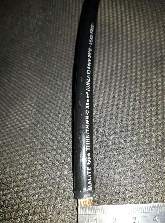
Let's tie up the loose ends (pun unintended) before I part with all critical information gained (before we disturb hbiss more). Well. I bought 1 meter of 38mm^2 (between AWG 2 and 1) because the electrician violated the bending rule of the feeder between main panel and subpanel (just short distance needing only 1 meter wires). I was taught that the bending radius should be outside diameter multiply by 8 and it shouldn't be bent more than once. He bent it 4 times. So I'll ask the contractor to give me more knowledgeable electrician. Consider me as engineer just verifying the electrical contractor quality of works.

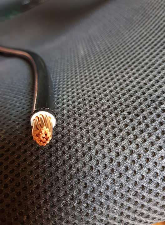
The following is the exact measurement of the conductor diameter of the Phelps Dodge 38mm^2 wire.

b2rjIv.jpg


It measures 8mm. In the Phelph Dodge table. The conductor diameter is listed as 7.8mm see https://phelpsdodge.com.ph/wp-content/uploads/2015/07/COPPER-BUILDING-WIRE-TYPE-THHNTHWN-21.pdf


I counted 20 individual cooper strands:

dFw6zl.jpg


Now let's talk about your AWG 1. In this web site:
http://www.panduit.com/heiler/SelectionGuides/WW-WASG03 Electrical Wire Sizes-WEB 7-7-11.pdf

The AWG 1 conductor has range of 7.3 to 8.4mm. How come the range is big? What is your most popular wiring brand and what is the actual conductor size in diameter?

How many strands inside each AWG 1?

How do you think they compute the 38mm^2 or 42.41mm^2 in AWG 1? First. Let's take the diameter of 8mm. The Area is computed to be 53mm^2. See https://www.omnicalculator.com/math/circumference
For your AWG 1 conductor size of 8mm. How did they come up with 42.41mm^2? Is it based on the strands? How many standard for AWG 1?

I've been contemplating your statement "part of me thinks that your wire isn't actually 38mm2 but 42.41mm2 listed as 38mm2." Why do you think they would do that? Won't it be better to just use the American AWG 1 as 42.41mm^2 instead of using 38mm^2?
 

mbrooke

Batteries Included
Location
United States
Occupation
Technician
I didn't just think up the questions. All my questions were due to actual applications issues:

3pqfvs.jpg


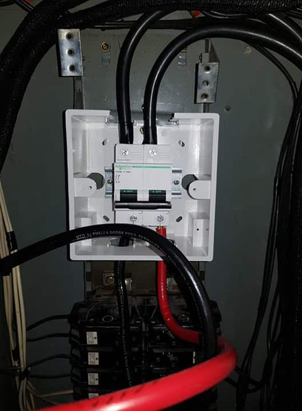
The electrician is migrating the panel from plug in to din rail and he bends the wires up and down. So I wonder how many times it can happen before micro cracks in the cooper can occur. I was not asking about the radius which we know but trying to bend with minimum radius up or down (or in opposite directions). If he does it 10 times, the wire can fracture. It's 30mm^2 or exactly between AWG 3 and AWG 2. But I wonder if less than 5 times, how would the wires behave.

Question- I'm sure I missed it- but why are you replacing that panel?
 

mbrooke

Batteries Included
Location
United States
Occupation
Technician
[I see. This explains why a 5mA GFCI can protect an entire house without leakages because all the devices were isolated. Should there be EGC or GEC. Then it can nuisance trip on dielectric insulation decay and current leakages to the EGC or GEC.

Yup- they are for the most part isolated.

Keep in mind the wires are still capacitively coupled to earth as well.

I know EGC is important so in the event of ground fault, it should trip the regular breaker immediately without waiting for a person and a ground via GFCI, which is only used for backup in the US.

Yup- correct.

But if the appliances have GEC. It should trip the GFCI as well so GEC should be at least a minimum. Hence will assign local electrical engineers for possible GEC installation and breaking concrete in the parking area next time.


In theory this would work.
 

tersh

Senior Member
Location
new york
Question- I'm sure I missed it- but why are you replacing that panel?

The panel was locally made. The bus bar stubs are not exactly 90 degrees but bent. All our panels were locally made and like that. When i bought the Siemens load center..they were exactly angled at 90 degrees..so impressive. When i learnt the breakers were just 1-pole and only of two pole trips..then rather than buying new double pole plug in breakers. May as well replace them with din rail. Most of our new home panels are din rail based now. But the electrical contractor and electricians im acquainted only have experienced with bolt on and plug in panels. So i need to look for contractor familiar with din rail.

Btw dont miss msg 22. Maybe your AWG 1 only has 12 strands? It equates to greater area perhaps totally 42.41mm^2 where our 38mm^2 were comprised of smaller 2mm^2 stand size? We can compute by summing the areas of individual stands.
 

mbrooke

Batteries Included
Location
United States
Occupation
Technician
The panel was locally made. The bus bar stubs are not exactly 90 degrees but bent. All our panels were locally made and like that. When i bought the Siemens load center..they were exactly angled at 90 degrees..so impressive. When i learnt the breakers were just 1-pole and only of two pole trips..then rather than buying new double pole plug in breakers. May as well replace them with din rail. Most of our new home panels are din rail based now. But the electrical contractor and electricians im acquainted only have experienced with bolt on and plug in panels. So i need to look for contractor familiar with din rail.

Btw dont miss msg 22. Maybe your AWG 1 only has 12 strands? It equates to greater area perhaps totally 42.41mm^2 where our 38mm^2 were comprised of smaller 2mm^2 stand size? We can compute by summing the areas of individual stands.

Makes sense.


Here are the number of strands for one very common brand that we use:


https://www.southwire.com/ProductCatalog/XTEInterfaceServlet?contentKey=prodcatsheet276
 

kwired

Electron manager
Location
NE Nebraska
The panel was locally made. The bus bar stubs are not exactly 90 degrees but bent. All our panels were locally made and like that. When i bought the Siemens load center..they were exactly angled at 90 degrees..so impressive. When i learnt the breakers were just 1-pole and only of two pole trips..then rather than buying new double pole plug in breakers. May as well replace them with din rail. Most of our new home panels are din rail based now. But the electrical contractor and electricians im acquainted only have experienced with bolt on and plug in panels. So i need to look for contractor familiar with din rail.

Btw dont miss msg 22. Maybe your AWG 1 only has 12 strands? It equates to greater area perhaps totally 42.41mm^2 where our 38mm^2 were comprised of smaller 2mm^2 stand size? We can compute by summing the areas of individual stands.
Number of strands has to do with how well those strands can be arranged into a circular pattern. Standard numbers are 1, 7, 19, 37,61. If you only had 12 strands all the same size, you can't make a circle with them without excessive gaps in the circle.
 

tersh

Senior Member
Location
new york
Very good :thumbsup:


A handle tie alone is not common trip. Meaning if one side trips, it will not kick off the other. But close enough- technically code does not require common trip for a straight 240 volt circuit.


I know what this is about- because I discovered it by mistake when playing with a few GE breakers I took apart.


If you take an older 2 pole common trip GE breaker, and then remove the handle tie, then turn one of the poles to off, were you to short circuit/over load the other pole thats still on it would jam trying to trip.

Reason I found being that when one pole is switched off, the bulky common trip mechanism starts to lean forward. When the other pole unlatches, its catch hits the leaning forward mechanism and snags on it. This is a design flaw in older GE breakers under 40amps- but I do not entirely blame GE as double pole breakers are not intended to have their handle ties removed and used as 2 single pole breakers. But despite being a code violation to modify stuff like that, I've seen it done on a few occasions in the US when an electrician ran out of singles on his truck. Fortunately the modern GE, Homeline and Square D breakers I also played with did not jam in this mode.


So to answer the question I doubt those breakers are counterfeit, it is normal for GE breakers to jam like that when the handle tie is removed.


Regarding breaker compatibility- stick with the same manufacturer as who made the panel. What will work in your local panels I have no idea. But if GE has been getting the job done I'd stick with GE.

I realized you were describing the 3 pole GE breakers (with arc flash damage) I just "teardown". I lost both springs when they flew into my table full of things. I'll look for them tomorrow before I try what you did. But I need to know something. When they jammed. Can they get back to normal by putting back the common handle and switching them to off or on. Or are they permanently defective? How do you get them back to normal?
 

tersh

Senior Member
Location
new york
Very good :thumbsup:


A handle tie alone is not common trip. Meaning if one side trips, it will not kick off the other. But close enough- technically code does not require common trip for a straight 240 volt circuit.


I know what this is about- because I discovered it by mistake when playing with a few GE breakers I took apart.


If you take an older 2 pole common trip GE breaker, and then remove the handle tie, then turn one of the poles to off, were you to short circuit/over load the other pole thats still on it would jam trying to trip.

Reason I found being that when one pole is switched off, the bulky common trip mechanism starts to lean forward. When the other pole unlatches, its catch hits the leaning forward mechanism and snags on it. This is a design flaw in older GE breakers under 40amps- but I do not entirely blame GE as double pole breakers are not intended to have their handle ties removed and used as 2 single pole breakers. But despite being a code violation to modify stuff like that, I've seen it done on a few occasions in the US when an electrician ran out of singles on his truck. Fortunately the modern GE, Homeline and Square D breakers I also played with did not jam in this mode.


So to answer the question I doubt those breakers are counterfeit, it is normal for GE breakers to jam like that when the handle tie is removed.


Regarding breaker compatibility- stick with the same manufacturer as who made the panel. What will work in your local panels I have no idea. But if GE has been getting the job done I'd stick with GE.

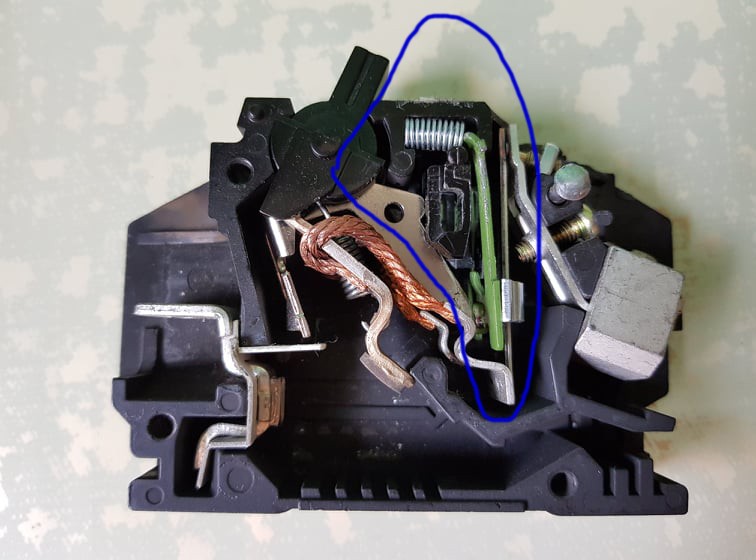
mbrooke. I'm trying to duplicate your jamming experiences. This is important to me because we may tolerate no EGC, no GEC, even arc flashing threshold residential panels, but not counterfeit breakers. Lol.

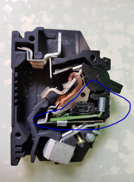
In the GE breaker, the area shown inside the blue is independent of the On and Off lever. I mean, even when I turned it on and off. The components inside the blue area didn't move.

0pvG77.jpg


Here I took video turning the breaker off and the common trip not moving:


The common trip didn't move forward. It seemed independent of the on and off switching. How did you get it to move? I want to repeat what you experienced. Did you see the common trip piece move when the unit cover was opened or closed? When one opens a GE breaker, there are 3 areas where it must be pressed by the cover or it will go unaligned. It's the most difficult breaker I have worked with (for many hours) scratching by fingers because I had to press many areas at once just to try turning it on, off or trip it or reset it. Without the cover, the common trip can indeed move because of the misalignment. But when it is already covered, it is fixed (the blue area above). Please share how to duplicate it. Also when it's jam. How do you unjam it? By simply turning it on and off again with full covers on?

I need to know because there are reports of hundreds of thousands of counterfeit breakers in the world. If what the guy in the province experienced was a counterfeit breakers. I may need to replace all my GE in the office building, and it will cost a lot. So I need to delve into this issue. Thanks.
 

LarryFine

Master Electrician Electric Contractor Richmond VA
Location
Henrico County, VA
Occupation
Electrical Contractor
I wouldn't expect the common-trip link to move when manually flipping the breaker; that's what the handle tie is for. The tripping mechanism doesn't depend on handle movement to trip, either internally or through the common-trip link.

In other words, the link tells the other pole(s) that a breaker has tripped, not that the handle has moved.
 

mbrooke

Batteries Included
Location
United States
Occupation
Technician
mbrooke. I'm trying to duplicate your jamming experiences. This is important to me because we may tolerate no EGC, no GEC, even arc flashing threshold residential panels, but not counterfeit breakers. Lol.

In the GE breaker, the area shown inside the blue is independent of the On and Off lever. I mean, even when I turned it on and off. The components inside the blue area didn't move.

0pvG77.jpg


Here I took video turning the breaker off and the common trip not moving:


The common trip didn't move forward. It seemed independent of the on and off switching. How did you get it to move? I want to repeat what you experienced. Did you see the common trip piece move when the unit cover was opened or closed? When one opens a GE breaker, there are 3 areas where it must be pressed by the cover or it will go unaligned. It's the most difficult breaker I have worked with (for many hours) scratching by fingers because I had to press many areas at once just to try turning it on, off or trip it or reset it. Without the cover, the common trip can indeed move because of the misalignment. But when it is already covered, it is fixed (the blue area above). Please share how to duplicate it. Also when it's jam. How do you unjam it? By simply turning it on and off again with full covers on?

I need to know because there are reports of hundreds of thousands of counterfeit breakers in the world. If what the guy in the province experienced was a counterfeit breakers. I may need to replace all my GE in the office building, and it will cost a lot. So I need to delve into this issue. Thanks.

Do you have a 2 pole 20? Break the case only where they bimetal, common trip and pole piece will be exposed- its better to to have the other moving parts aligned and held in place by the case.


Removed the handle tie. Make sure both poles are on. Then switch the unexposed pole to off. Take a paper clip and move the bi metal back far enough to unlatch the exposed (on) pole. When it unlatches, the latch shoe will go down but get caught on the common trip preventing that pole from opening.


This is not an issue with counterfeit breakers, but genuine GE breaker from the 70s-90s.
 

tersh

Senior Member
Location
new york
Do you have a 2 pole 20? Break the case only where they bimetal, common trip and pole piece will be exposed- its better to to have the other moving parts aligned and held in place by the case.


Removed the handle tie. Make sure both poles are on. Then switch the unexposed pole to off. Take a paper clip and move the bi metal back far enough to unlatch the exposed (on) pole. When it unlatches, the latch shoe will go down but get caught on the common trip preventing that pole from opening.


This is not an issue with counterfeit breakers, but genuine GE breaker from the 70s-90s.

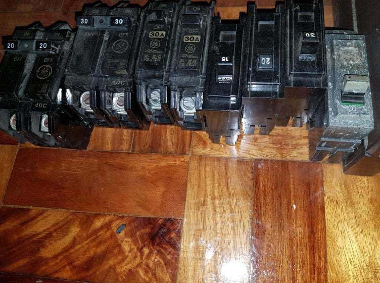
I have many extra breakers:

C0xOAc.jpg


More at the attics. Some from my old office I rented a decade ago.

ey3wAy.jpg


Is the above 20A bolt on what you mean?

It took me an hour to remove the back screws in the arc flashed 3-pole breaker the other day. I used drilled on the ends but it wasn't removed. How do you easily open the case (should it need to be opened)?

DhBOFB.jpg


These are bought about 2010. How come GE Singapore still have them when these are supposed to be stock in the 1990s?

I really need to see what you are saying for quality check since all my breakers at office building is GE just like that. But how come I didn't notice it in the arc flashed 100A 3 pole model with the same black common trip piece? In essence. Are you saying when the other pole is switched to OFF position, it moves the white common trip lever? Because without it moving, it shouldn't affect the other pole at all.
 

mbrooke

Batteries Included
Location
United States
Occupation
Technician
Yes, try a 20 amp.


Do it like I did with the rivets and part of the case still in place to hold the parts down:
 

Attachments

  • GE 20amps 2 pole.jpg
    GE 20amps 2 pole.jpg
    77.6 KB · Views: 0

tersh

Senior Member
Location
new york
Yes, try a 20 amp.

GWfkrj.jpg


Do it like I did with the rivets and part of the case still in place to hold the parts down:

The internal parts of your teardown is very similar to my arc flashed 3-pole. I hold the spring tight so many times my fingers hurted and I handled it for 2 hours yesterday so I'm very familiar with the mechanism. I tripped it many times stand alone.

XvESHb.jpg


When it unlatched, the arc flashed 3-pole looked like this:

SnDIpV.jpg


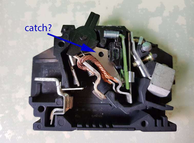
When it tripped. The lever goes down without the black common trip blocking it. Let's go back to your statement before. You said: "Reason I found being that when one pole is switched off, the bulky common trip mechanism starts to lean forward. When the other pole unlatches, its catch hits the leaning forward mechanism and snags on it."

When you said "starts to lean forward". Did you mean the black common trip going up or down (which is your "forward"?) or sideways? And when it unlatches, how can the catch (which is the green bimetallic strip, right?) hit the learning forward mechanism and snag on it? I just want to imagine or visualize what you were saying first before opening the 20A because I have handled the 3-pole for 2 hours and move it back and forth a hundred times (due to the spring kept jumping out of the case, one even got lost, etc.) so should be able to get what you mean if I understood your descriptions. Thanks.
 

mbrooke

Batteries Included
Location
United States
Occupation
Technician
The internal parts of your teardown is very similar to my arc flashed 3-pole. I hold the spring tight so many times my fingers hurted and I handled it for 2 hours yesterday so I'm very familiar with the mechanism. I tripped it many times stand alone.

XvESHb.jpg


When it unlatched, the arc flashed 3-pole looked like this:

SnDIpV.jpg


When it tripped. The lever goes down without the black common trip blocking it. Let's go back to your statement before. You said: "Reason I found being that when one pole is switched off, the bulky common trip mechanism starts to lean forward. When the other pole unlatches, its catch hits the leaning forward mechanism and snags on it."

When you said "starts to lean forward". Did you mean the black common trip going up or down (which is your "forward"?) or sideways? And when it unlatches, how can the catch (which is the green bimetallic strip, right?) hit the learning forward mechanism and snag on it? I just want to imagine or visualize what you were saying first before opening the 20A because I have handled the 3-pole for 2 hours and move it back and forth a hundred times (due to the spring kept jumping out of the case, one even got lost, etc.) so should be able to get what you mean if I understood your descriptions. Thanks.

Don't see the white bar going going through the common trip.


When I say it leans forward is doing just that toward the left.
 

tersh

Senior Member
Location
new york
Don't see the white bar going going through the common trip.


When I say it leans forward is doing just that toward the left.

When I tried to open the arc flashed 3-pole breaker 2 days ago. I used the drill many times and so many carbon in air. That's why I won't be using any drill even in cracking open the housing of the 20A to avoid inhaling any plastic. I opened it up only if it's so critical like examining the source of the arc flash. But without drill it's difficult to exactly to cut at the right spots.

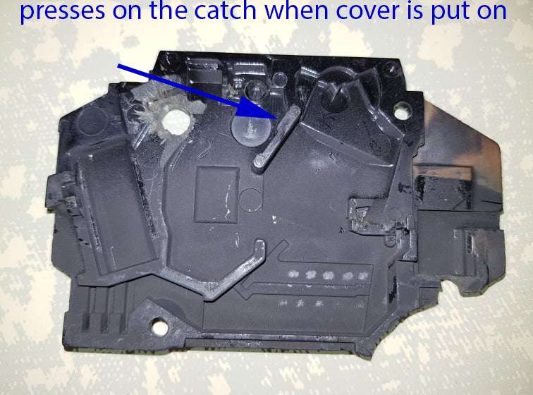
But then when you said the other partner jammed when you tried to trip it. Have you tried tripping it to intact breakers without cracking open the front of it. Because I noticed and in fact it was what giving me so much problems with it that if you don't put the cover over the breaker and the black line in second picture below pressing on the catch (which is the silver thing instead of the green thing, right?) it always jammed. Only when the cover is put on that it won't be jammed. Therefore in your GE test breaker, most accurate test would be tripping it without any opening in the breaker, like actually subjecting it to 20A current source or short? Have you done this? No I won't do this because it's dangerous. But just need to know if you can trip the partner without any opening. Because by opening the catch portion alone can jam it. I had problems for 2 hours working with it precisely because it kept jamming and I had to use screw driver to press on the catch so it can trip and not snag on the black common trip.

n4XTtB.jpg


GBbdO0.jpg
 

mbrooke

Batteries Included
Location
United States
Occupation
Technician
When I tried to open the arc flashed 3-pole breaker 2 days ago. I used the drill many times and so many carbon in air. That's why I won't be using any drill even in cracking open the housing of the 20A to avoid inhaling any plastic. I opened it up only if it's so critical like examining the source of the arc flash. But without drill it's difficult to exactly to cut at the right spots.


Use a screw driver to bend the case upwards trying to get it to crack at the 1/3 point- all you need is a way to expose the bimetal to get it to trip.

But then when you said the other partner jammed when you tried to trip it. Have you tried tripping it to intact breakers without cracking open the front of it.

Honestly, I have not. But I guess it could be replicated doing the same thing and whacking the breaker into your palm to get it to trip.


Because I noticed and in fact it was what giving me so much problems with it that if you don't put the cover over the breaker and the black line in second picture below pressing on the catch (which is the silver thing instead of the green thing, right?) it always jammed. Only when the cover is put on that it won't be jammed. Therefore in your GE test breaker, most accurate test would be tripping it without any opening in the breaker, like actually subjecting it to 20A current source or short? Have you done this? No I won't do this because it's dangerous. But just need to know if you can trip the partner without any opening. Because by opening the catch portion alone can jam it. I had problems for 2 hours working with it precisely because it kept jamming and I had to use screw driver to press on the catch so it can trip and not snag on the black common trip.

n4XTtB.jpg


GBbdO0.jpg


Well, you may be on to something. I had not thought of the covering playing that big a role in the common trip and maybe it does.

I'd try the experiment with a 20 making it trip and then measuring the continuity. Hopefully you are right Tersh.
 

tersh

Senior Member
Location
new york
Use a screw driver to bend the case upwards trying to get it to crack at the 1/3 point- all you need is a way to expose the bimetal to get it to trip.


Honestly, I have not. But I guess it could be replicated doing the same thing and whacking the breaker into your palm to get it to trip.


Well, you may be on to something. I had not thought of the covering playing that big a role in the common trip and maybe it does.

I'd try the experiment with a 20 making it trip and then measuring the continuity. Hopefully you are right Tersh.

fSNGnH.jpg


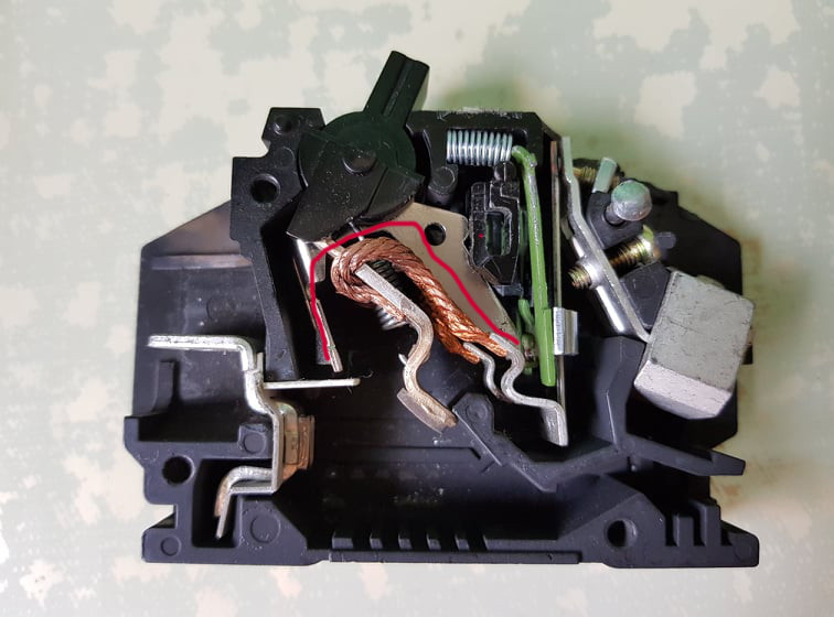
Without the cover pushing the whole catch down. I found the entire catch was misaligned (shown in red line above). So it can't trip. I had to use some tools to press the catch, but then the bimetal flew out. That was why it took me 2 hours just getting the hang of it. I had a hard time testing even just simple On and Off without cover. In the Siemens and Westinghouse. The mechanisms can work without the cover.

But then in your test unit. It was half covered. The left half side was covered. So it may be aligned after all? Hope you can find other ways to test it, like whacking it in the palm of your hands to get it to trip?

With covers fully on. If one removed the common handle, and put one side to off position, and the other partner still trips. Then the implication is the American who built the home in the province is using counterfeit breakers.

I read this:

"One of the most counterfeited electrical components is circuit breakers. These fake products may pose a number of safety and legal risks to consumers and businesses.

The market for counterfeit products cost businesses almost $250 billion in the U.S. each year and the global economy $500 billion annually. Siemens said contractors may find it difficult to distinguish counterfeit circuit breakers from ones made by legitimate companies and components. However, contractors can spot fake electrical products when they know to look for tell-tale signs, according to Siemens.
How to Spot Fake Circuit Breakers

Products Lacking Instructions, Warnings or Warranties

Products that are missing instructions or warranties is one of the first indicators that a product is not from an authentic manufacturer. Companies usually include instructions or warranties to show proof of purchase.

Packaging or Markings Are Missing or Different From Legitimate Products

For example, contractors may notice that product packaging may have the wrong colors. The products themselves may be designed incorrectly or not labeled with the country of origin, according to Schneider Electric.

Product Performance Is Unusual

Contractors who often handle the same products may note key differences in performance from fake products as opposed to authentic ones. For example, there could be product defects that cause the product to malfunction or break.

Product Price Is Too Low

While the price may seem too good to pass up, fake circuit breakers may be priced cheaply because they were made with inferior components.

"

mbrooke, Have you ever seen a counterfeit breaker. How does it look like? What if it looks so much like the original (even smell like the original) that it's almost indistinguishable except the counterfeit won't trip during a short?

In the American who built a house in the province with a Filipina. What if he got a unit where one half of the pole is genuine, while the partner is counterfeit?

Or maybe you were right that it's the mechanism. Hope you can help determine. Thank you.
 

mbrooke

Batteries Included
Location
United States
Occupation
Technician
fSNGnH.jpg


Without the cover pushing the whole catch down. I found the entire catch was misaligned (shown in red line above). So it can't trip. I had to use some tools to press the catch, but then the bimetal flew out. That was why it took me 2 hours just getting the hang of it. I had a hard time testing even just simple On and Off without cover. In the Siemens and Westinghouse. The mechanisms can work without the cover.


All observed and experienced correctly, the cover aligns and keeps things from flying out. Some brands are better at it then others, but even the cutler hammer breakers will have parts pop out at times.

But then in your test unit. It was half covered. The left half side was covered. So it may be aligned after all? Hope you can find other ways to test it, like whacking it in the palm of your hands to get it to trip?

The part you have traced out in red was aligned, but, that you mentioned it its possible the common trip was not aligned as well as I though it was.


With covers fully on. If one removed the common handle, and put one side to off position, and the other partner still trips. Then the implication is the American who built the home in the province is using counterfeit breakers.

I read this:

"One of the most counterfeited electrical components is circuit breakers. These fake products may pose a number of safety and legal risks to consumers and businesses.

The market for counterfeit products cost businesses almost $250 billion in the U.S. each year and the global economy $500 billion annually. Siemens said contractors may find it difficult to distinguish counterfeit circuit breakers from ones made by legitimate companies and components. However, contractors can spot fake electrical products when they know to look for tell-tale signs, according to Siemens.
How to Spot Fake Circuit Breakers

Products Lacking Instructions, Warnings or Warranties

Products that are missing instructions or warranties is one of the first indicators that a product is not from an authentic manufacturer. Companies usually include instructions or warranties to show proof of purchase.

Packaging or Markings Are Missing or Different From Legitimate Products

For example, contractors may notice that product packaging may have the wrong colors. The products themselves may be designed incorrectly or not labeled with the country of origin, according to Schneider Electric.

Product Performance Is Unusual

Contractors who often handle the same products may note key differences in performance from fake products as opposed to authentic ones. For example, there could be product defects that cause the product to malfunction or break.

Product Price Is Too Low

While the price may seem too good to pass up, fake circuit breakers may be priced cheaply because they were made with inferior components.

"

mbrooke, Have you ever seen a counterfeit breaker. How does it look like? What if it looks so much like the original (even smell like the original) that it's almost indistinguishable except the counterfeit won't trip during a short?

In the American who built a house in the province with a Filipina. What if he got a unit where one half of the pole is genuine, while the partner is counterfeit?

Or maybe you were right that it's the mechanism. Hope you can help determine. Thank you.


I'd think both poles would be counterfeit if so. All the parts are assembled at a single factory.


Only way to know is to test.


Another possibility is a manufacturing defect. I've had GE breakers broken right out of the box here in the US.


Regarding counterfeits, only way to know is a certification from the manufacturer. Some counterfeits are obvious as day, others are indistinguishable from the real thing. Especially when a US company opens up a factory in China building parts to their spec. Then the contract runs out and everything is left behind- only for them to start making counterfeit good using the same molds, spec, logos, intellectual property, ect as a reputable manufacturer.
 
Status
Not open for further replies.
Top