Circuit Breaker teardown and defective Siemens latching mechanism

Merry Christmas
Status
Not open for further replies.

tersh

Senior Member
Location
new york
As long as they both go in parellel, I've seen no issues.


I don't have any calipers with me, but from the looks of it your panel bausbars are thinner.


How old is your home panel and its breakers? If over 30 years old replacing it would not be a dumb move.


I still don't think they would be allowed. Jraef would know the full details, but IEC breakers in the US are only listed as supplementary over current devices or something to that effect. I may start a thread on that as I am just as curious as you...


In Europe with full house RCD or RCBO, where do they put the circuits of their lightings. Must a room with the lights and outlets be in the same circuits from load side of an RCD or GFCI? You may say should be separated so during lights out from one RCD tripping, the room still has outlets. But then won't it be better to install an emergency light plugged to an outlet in the room so in case the lights go out, at least the back up emergency lights would light up? If the lights and outlets were in different GFCI or RCD circuits. Then the emergency lights won't turn on. I've been thinking about this for days. Presently one 5mA 60A Siemens 2-pole GFCI breaker in the main breaker of my full house GFCI protection has the following loads:

1. 2.5 Hp room 1 aircon
2. 1.5 Hp room 2 aircon
3. 1 Hp room 3 aircon
4. Ground floor, 2nd floor and attic lights
5. attic outlets
6. kitchen outlets
7. Room 4 outlets
8. water pump
9. Sala 2Hp aircon
10. Washing machine

Each has separate breaker. But they are all served by one 5mA 60A Siemens GFCI breakers. So far it has not tripped even a single time.

If it trips, all the lights go out. However, the second floor outlets were in different GFCI breaker load out (30A). This won't turn on any emergency lights plugged into the outlets. If they are in the same circuits. The emergency lights would turn on when lights go out during a GFCI leakage current trip in one of the appliances. In Europe. How do they arrange the lights? Or maybe they plug the emergency lights right to the lighting circuit itself? How? Other ideas where to put lights in a full house RCD or GFCI protection dwelling?
 

mbrooke

Batteries Included
Location
United States
Occupation
Technician
fascinating thread tersh.
:thumbsup:
i'm moved to find some calipers ,and throw them in my worktruck to assess all these breaker buss bars of different types.

If in fact they do differ, in that there is no 'buss bar' standrad for all manufactuers , then i'm curious as to how 'universal breakers' (we have Eaton and T&B) could possibly be listed to address the difference?

Further, if indeed so....what good would adhereing to tourqe specifications be for any installer?:?

As to the whole counterfiet breaker scenario , our trade rage (which are basically monthly advertisments for manufacturers) ran full page ads of electricians behind bars a while ago.:happysad:


The reality being they were thwarting internet sales for their domestic distributors , ironically who procured their materials from the very same 3rd world sources that produced a line of fakery...


~RJ~

I'd be just as interested if you were to do that. I too want to know the differences.
 

mbrooke

Batteries Included
Location
United States
Occupation
Technician
In Europe with full house RCD or RCBO, where do they put the circuits of their lightings.

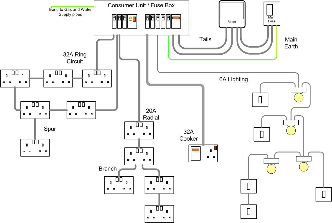
Typically on a separate circuit- often 6 amps and wired in 0.75 or 1mm2 wire.


BasicWiringLayout.gif


Must a room with the lights and outlets be in the same circuits from load side of an RCD or GFCI?


Typically the sockets are on one RCD and the lights on another for any one room.


So for example, if you had 2 RCDs for the whole home, RCD #1 would feed the down stairs sockets and upstairs lights while RCD #2 would feed the upstairs sockets and down stairs lights. That way a trip on any RCD would not remove all power to the room.


You may say should be separated so during lights out from one RCD tripping, the room still has outlets. But then won't it be better to install an emergency light plugged to an outlet in the room so in case the lights go out, at least the back up emergency lights would light up?


I would not do this for a home. Because who is going to change the battery in the emergency light? Perhaps yourself yes, but the future owners? Would they know that an RCD tripping would remove all the lights?


If the lights and outlets were in different GFCI or RCD circuits. Then the emergency lights won't turn on. I've been thinking about this for days. Presently one 5mA 60A Siemens 2-pole GFCI breaker in the main breaker of my full house GFCI protection has the following loads:

1. 2.5 Hp room 1 aircon
2. 1.5 Hp room 2 aircon
3. 1 Hp room 3 aircon
4. Ground floor, 2nd floor and attic lights
5. attic outlets
6. kitchen outlets
7. Room 4 outlets
8. water pump
9. Sala 2Hp aircon
10. Washing machine

Each has separate breaker. But they are all served by one 5mA 60A Siemens GFCI breakers. So far it has not tripped even a single time.

Ok- but in Europe all that would in the very minimum be served by a 30ma RCD. The lack of EGC might be helping to not go over 5ma.


If it trips, all the lights go out. However, the second floor outlets were in different GFCI breaker load out (30A). This won't turn on any emergency lights plugged into the outlets. If they are in the same circuits. The emergency lights would turn on when lights go out during a GFCI leakage current trip in one of the appliances. In Europe. How do they arrange the lights? Or maybe they plug the emergency lights right to the lighting circuit itself? How? Other ideas where to put lights in a full house RCD or GFCI protection dwelling?

If the main RCD is a delayed trip type, I would not worry about it becase the branch circuit RCD would trip first.


If you do not have an RCD for each branch circuit, then I would do 2 none delayed sub-main RCDs each taking half the load.


Here is a UK example:


NHRS15SSLHI_2.jpg


a54299b29db578b92ef905f8e78bdb5a.jpg
 

tersh

Senior Member
Location
new york
Typically on a separate circuit- often 6 amps and wired in 0.75 or 1mm2 wire.


Typically the sockets are on one RCD and the lights on another for any one room.


So for example, if you had 2 RCDs for the whole home, RCD #1 would feed the down stairs sockets and upstairs lights while RCD #2 would feed the upstairs sockets and down stairs lights. That way a trip on any RCD would not remove all power to the room.


I would not do this for a home. Because who is going to change the battery in the emergency light? Perhaps yourself yes, but the future owners? Would they know that an RCD tripping would remove all the lights?


Ok- but in Europe all that would in the very minimum be served by a 30ma RCD. The lack of EGC might be helping to not go over 5ma.


If the main RCD is a delayed trip type, I would not worry about it becase the branch circuit RCD would trip first.


If you do not have an RCD for each branch circuit, then I would do 2 none delayed sub-main RCDs each taking half the load.


Here is a UK example:

Thanks for the information. So for those with outlets and lights of room in different RCD or GFCI circuits. So they must have a table lamp or something to turn on when the lights trip out.

I will not be using any RCDs or RCBOs but only six 6pcs 5mA GCFI breakers powering the entire house. The reason I can't yet get the electrician to install any din rail MCBs to replace the 1-pole GE breakers in local plug in panel was because for days I kept thinking how best to arrange all the loads (especially lightings) and what respective circuits to put them on from each GFCI breaker. Right my load distribution were just temporary. This is my main panel/breakers now:

sMMgle.jpg


If you have ideas how Americans with same setup as mine is distributing the loads and circuits for the GFCI breaker loads, let me know. Or more example of RCDs/RCBOs in Europe so I know the typical style or technique for load distribution.

Also I think Mike Holt said in year 2020 or so GFCI would be in every circuit of American home. I'm just trying to implement his ideas now :)
 
Last edited:

mbrooke

Batteries Included
Location
United States
Occupation
Technician
Thanks for the information. So for those with outlets and lights of room in different RCD or GFCI circuits. So they must have a table lamp or something to turn on when the lights trip out.

That is the idea. Or a TV running. Anything that might add some light.


I will not be using any RCDs or RCBOs but only six 6pcs 5mA GCFI breakers powering the entire house. The reason I can't yet get the electrician to install any din rail MCBs to replace the 1-pole GE breakers in local plug in panel was because for days I kept thinking how best to arrange all the loads (especially lightings) and what respective circuits to put them on from each GFCI breaker. Right my load distribution were just temporary. This is my main panel/breakers now:


I'm confused- what is feeding this panel? And what was the panel with all the single pole breakers you posted earlier?

If you have ideas how Americans with same setup as mine is distributing the loads and circuits for the GFCI breaker loads, let me know. Or more example of RCDs/RCBOs in Europe so I know the typical style or technique for load distribution.

Typically in US homes lights and outlets are on the same circuit. Of course this excludes the kitchen counter outlets and the dinning room outlets. In commercial however lights are typically independent of outlets even when the service to the building is 120/208Y.


Also I think Mike Holt said in year 2020 or so GFCI would be in every circuit of American home. I'm just trying to implement his ideas now :)

It will eventually happen.
 

tersh

Senior Member
Location
new york
That is the idea. Or a TV running. Anything that might add some light.


I'm confused- what is feeding this panel? And what was the panel with all the single pole breakers you posted earlier?

bzeFg1.jpg


What's feeding it is the Schneider din rail MCB 125A breaker (that replaced the GE TDQ that originally powered the GE plug in bus bar) The single pole breakers bus bar was isolated and became an output of the 60A Siemens GFCI breaker. It's already replaced with AWG 6 for 60A 75C table in actual. The other loads like fridges and tv, rice cooker, microwave etc. were directly connected to the 5 other GFCI Breakers. After the lightings and outlets combinations were decided and I can find electrician with experience in din rail MCBs. Then he will totally remove the single pole breakers and plug in bus bar to replace with all din rail MCBs. I just need to find one familiar how to arrange all the din rail MCBs using the original chassis. The din rail MCBs would be the subpanel(s) of the now main Siemens panel with 6 GFCI breakers.


Typically in US homes lights and outlets are on the same circuit. Of course this excludes the kitchen counter outlets and the dinning room outlets. In commercial however lights are typically independent of outlets even when the service to the building is 120/208Y.


It will eventually happen.
 
Last edited:

tersh

Senior Member
Location
new york
I'm still confused- What panel does the incoming POCO power feed first?

Inside the house it feeds this stand alone panel first which is located right side of the two:

Kbx8w1.jpg


Then it goes to the Schneider din rail MCB 125A breaker directly feeding the Siemens panel.

So it's like it passes through the GE panel which is between them. But the Schneider MCB 125A doesn't power the GE bus bar but directly feeding the Siemens panel.

jdMNr8.jpg


Note the original panel has the GE bus bar and main breaker isolated already. The original TDQ main breaker was removed.
 
Last edited:

tersh

Senior Member
Location
new york
Can you post the GE panel as it stands now?


Thank you for clearing things up. :)

It's very ugly now with so many wires crisscrossing. Imagine the loads in the original GE breakers were diverted to the GFCI breakers. While some remains. It's just temporary. When they were replaced with din rail MCBs. Then they would look nice.

The picture would attract the full wrath of NEC because it violates every rule in the book.. Lol. It's just temporary but due to the ugliness.. people may get scared believing it is permanent. Lol.

I'll discuss with an electrician tomorrow if they know how put din rail MCBs. Thanks for the tips the lighting and outlets in a room must not be put on same GFCI. I was planning to put emergency light. But a wall light connected to outlet with switch would be better idea. If you know what kind of wall lamps the Europeans RCDers use. Please let me know. Thank you!
 

mbrooke

Batteries Included
Location
United States
Occupation
Technician
It's very ugly now with so many wires crisscrossing. Imagine the loads in the original GE breakers were diverted to the GFCI breakers. While some remains. It's just temporary. When they were replaced with din rail MCBs. Then they would look nice.

The picture would attract the full wrath of NEC because it violates every rule in the book.. Lol. It's just temporary but due to the ugliness.. people may get scared believing it is permanent. Lol.

I'll discuss with an electrician tomorrow if they know how put din rail MCBs. Thanks for the tips the lighting and outlets in a room must not be put on same GFCI. I was planning to put emergency light. But a wall light connected to outlet with switch would be better idea. If you know what kind of wall lamps the Europeans RCDers use. Please let me know. Thank you!


Doubt it would scare much- its temporary after all.


Regarding wall lamps pick what you like...


Which leads me to ask- what type of light bulb sockets do you use? Since there is no neutral.
 

tersh

Senior Member
Location
new york
Doubt it would scare much- its temporary after all.

I may post it tomorrow.


Regarding wall lamps pick what you like...


Which leads me to ask- what type of light bulb sockets do you use? Since there is no neutral.

The light bulb sockets are the typical round shape like this in my room now:

9wETVs.jpg


It's 11:35pm now. I'll sleep now. Talk to you tom. Thanks.
 

tersh

Senior Member
Location
new york
I mean does the screw shell stay live when unscrewing the bulb?


Usually the electrician just replaced the bulb by unscrewing it and putting it back. Since he hold the bulb with it power off, then he just screw it back. Not live because the bulb can suddenly become hot.


Ok. The following is inside the original panel which is just temporary and which I warned can incur the wrath of NEC. Lol.

S9UDBE.jpg


But let me emphasize it is just temporary. When I finally find contractors who can replace the lower portion with din rail MCBs (all new condos and houses use these now as the plug in bus bar are huge and ugly). Then it will be pretty and all the wires will be neat. Note the black wires upper right were newly installed last year to the bath heaters that took outside paths. Two 30A GFCI breakers separately serve the bath heaters with AWG 10 wires. The mica wires are just cover for all of the AWG 10 wires.

Do you think it's better to the din rail MCBs like these (horizontally in many rows):

SNbdTf.jpg


Or is it better to put the din rail MCBs sideway in one vertical line only? Any in Europe with sideways din rail MCBs?

NAhayp.jpg


What do you think?

Also since one panel was mount outside, one was flushed and there are feeders between them. I know it is difficult to cover, therefore the electrical contractor will need to fabricate special cover that can make the wires go out at upper mid left side (neatly) with the rest of chassis covered.
 

mbrooke

Batteries Included
Location
United States
Occupation
Technician
Usually the electrician just replaced the bulb by unscrewing it and putting it back. Since he hold the bulb with it power off, then he just screw it back. Not live because the bulb can suddenly become hot.

So you break both legs to the lights?


Ok. The following is inside the original panel which is just temporary and which I warned can incur the wrath of NEC. Lol.

S9UDBE.jpg


No wrath, its temporary as you are in the process of having your panel changed.


But let me emphasize it is just temporary. When I finally find contractors who can replace the lower portion with din rail MCBs (all new condos and houses use these now as the plug in bus bar are huge and ugly). Then it will be pretty and all the wires will be neat. Note the black wires upper right were newly installed last year to the bath heaters that took outside paths. Two 30A GFCI breakers separately serve the bath heaters with AWG 10 wires. The mica wires are just cover for all of the AWG 10 wires.

Do you think it's better to the din rail MCBs like these (horizontally in many rows):

SNbdTf.jpg


Or is it better to put the din rail MCBs sideway in one vertical line only? Any in Europe with sideways din rail MCBs?


What do you think?

Also since one panel was mount outside, one was flushed and there are feeders between them. I know it is difficult to cover, therefore the electrical contractor will need to fabricate special cover that can make the wires go out at upper mid left side (neatly) with the rest of chassis covered.

In Europe DIN rail breakers are usually horizontally installed going left to right...
 

kwired

Electron manager
Location
NE Nebraska
I mean does the screw shell stay live when unscrewing the bulb?
He is asking if the screw shell of the lampholder has voltage potential when the switch is off? Here such screw shell style is supposed to be connected to the grounded circuit conductor - when grounded conductor is used. This partly because it is easier to come in contact with the screwshell than the center pin and there will be little or no voltage to other ground potential objects should you contact it. One way you can lessen risks where you don't use a grounded conductor there is to switch both lines to the lampholder.
 

mbrooke

Batteries Included
Location
United States
Occupation
Technician
He is asking if the screw shell of the lampholder has voltage potential when the switch is off? Here such screw shell style is supposed to be connected to the grounded circuit conductor - when grounded conductor is used. This partly because it is easier to come in contact with the screwshell than the center pin and there will be little or no voltage to other ground potential objects should you contact it. One way you can lessen risks where you don't use a grounded conductor there is to switch both lines to the lampholder.

That or to switch the screw shell- when you unscrew the bulb the center pin will break first theoretically leaving the shell cold.
 

tersh

Senior Member
Location
new york
He is asking if the screw shell of the lampholder has voltage potential when the switch is off? Here such screw shell style is supposed to be connected to the grounded circuit conductor - when grounded conductor is used. This partly because it is easier to come in contact with the screwshell than the center pin and there will be little or no voltage to other ground potential objects should you contact it. One way you can lessen risks where you don't use a grounded conductor there is to switch both lines to the lampholder.


For decades. I have never seen any electrician or domestic helpers or even owners turn off the circuit breaker just to change light bulb. The reason is because the screw shell is hidden inside with porcelain or plastic casing outside (see picture below of typical socket). So when you hold the light bulb at the lower half end. There is just no way to touch the screw shell unless the person is blind :) (but then he could still feel where the lower half of the light bulb is)

4mMH2E.jpg
 
Status
Not open for further replies.
Top