Confusion on Ground fault protection for equipment.

Status
Not open for further replies.

electrofelon

Senior Member
Location
Cherry Valley NY, Seattle, WA
Occupation
Electrician
Looking for a little clarification here. I am not real familiar with these systems, in fact this is the first time I have installed a new service or SDS with GFPE. Up till now, I always seem to get around the requirement by using MLO's with multiple service disconnects.

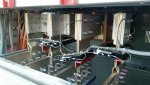
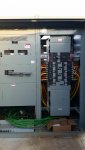
We have a 3000 amp switchboard with a 3000 amp BPS main. This is actually a SDS not a service. The Unit was all factory built and assembled. After pulling the feeders, I was getting set to make terminations. I knew it was a GFPE system so I began to look at the equipment in more detail to make sure I was landing the neutrals and ground on the proper busses. There is a CT on each phase, but not one on the system bonding jumper. I assume that makes this a zero sequence type not a residual type correct? What I am confused by is there is a sticker near the neutral buss that reads "do not land any grounding conductors on this buss or GFP will be defeated." Was this sticker erroneously applied as it seems this would only apply to a residual GFP system, correct? I would appreciate some clarification. Thanks.
 
Connecting an EGC to the neutral bus could provide an alternative path between there and the POCO or SDS secondary which bypasses the current transformer on the neutral wire.
That would cause the zero sequence sum to be non-zero.
This mechanism assumes that the EGC landed incorrectly also has some incidental continuity to earth or to another neutral wire. Which is not unlikely given that parallel connections within the EGC/GES network are OK and common.

Sent from my XT1585 using Tapatalk

But there is no ct on the neutral, and the ground buss is solidly connected to the neutral buss. So why is that label and how is any ground fault protection provided?
 
If you need to distinguish between neutral current and ground current you must measure one of them.

With three (3) phase CTs, you will only know when zero sequence currents are present, not which path they take. You need at least N-1 paths measured.

Are you absolutely sure the neutral or ground is not being measured?
 
That would be rare in comparison to the gear I see. AS neutral CT is usually present. Perhaps it was designed for no neutral load ?
 
I think your earth fault relay is actually residually connected to ground with over current relays connected only in two phases. Any separate connection of neutral with ground other than through E/F relay would partly bypass E/F relay and hence the warning.
 
If you have 3 separate CTs on the phase conductors, it's not Zero Sequence, that requires a single ZSCT around all of the conductors. Separate CTs implies Residual Current Detection.

IMG_0282.JPG
 
If you have 3 separate CTs on the phase conductors, it's not Zero Sequence, that requires a single ZSCT around all of the conductors. Separate CTs implies Residual Current Detection.
They may still refer to zero sequence current because it is calculated rather than measured. The neutral CT is just separating acceptable zero sequence current (neutral current) from unacceptable zero sequence current (ground current).
 
Thanks for the comments. I am reasonably certain that it was just the three cts on the phases, bUT I will be on site tomorrow and will double check. In the meantime maybe backing up a little would help to make sure I am correctly understanding what we are trying to do with GFP. Why not just monitor the MBJ or sbj? What types of faults are we looking for?
 
Thanks for the comments. I am reasonably certain that it was just the three cts on the phases, bUT I will be on site tomorrow and will double check. In the meantime maybe backing up a little would help to make sure I am correctly understanding what we are trying to do with GFP. Why not just monitor the MBJ or sbj? What types of faults are we looking for?
You are looking for any fault to something other than a phase or neutral conductor.

You could monitor the MBJ if you are sure it is the ONLY ground path back to the source neutral or than you have monitored all the other ground paths back as well. Better to monitor vector sum the load phase and neutral currents and react to a non-zero sum. So, sum all intended paths and anything else is....unintended.

The are other uses for ground relays.

I am aware there has been a history of burn downs with such systems, hence the 230.95 requirement. So what usually happens, is the fault a higher impedence fault thus the fault isn't picked up by an ocpd!
 
I am aware there has been a history of burn downs with such systems, hence the 230.95 requirement. So what usually happens, is the fault a higher impedence fault thus the fault isn't picked up by an ocpd!
yes, or the ocpd reaction is not fast enough. We are preventing not only high current fires but also protecting people/equipment from current levels that may not be high enough to even start a raging fire.
 
GFP Systems

GFP Systems

From what I recall there are (3) types of GFP systems:
1. Zero Sequence with 1 CT around all 4 phases and neutral on a 4 wire system.
2, Residual with CTs around the 3 phases and neutral (NOT NEUTRAL TO GROUND STRAP) on a 4 wire system.
3. Ground Strap with 1 CT on the neutral to ground strap (buss/ cable) on a 4 wire system.
There are systems that provide GFP on 4 wire schemes that only have CTs on the phase conductors only
if they fed loads that are only 3 phase in nature (transformers, motors) and there is no neutral landing for customer connections (because the source is a Y connected transformer secondary with a grounded neutral.)
My take on this is as follows:
You stated there is a warning label that states do not land any Ground Cables here. This is usually found downstream of the neutral CT of zero sequence or residual systems. THE NEUTRAL CAN ONLY BE GROUNDED AT ONE POINT UPSTREAM OF THE NEUTRAL CT.
This tells me you have a residual system and the factory left out theCT on the neutral bus/ cable upstream of the neutral landing bus as any ground fault current would return to the XO point as normal load current and defeat the GF protection. This was a common mistake made prior to GFP when the neutral was treated the same as the ground conductor.
 
Ok I think all is well and I have cried wolf. There is a Neutral ct, it just wasn't in an intuitive spot. The label that says to not land grounding conductors here is on the neutral buss on the customer side of the neutral CT. The ground buss is on the utility side of the neutral CT. The SBJ is on the utility side of the neutral CT. I think all is good in the world.
 
Ok I think all is well and I have cried wolf. There is a Neutral ct, it just wasn't in an intuitive spot. The label that says to not land grounding conductors here is on the neutral buss on the customer side of the neutral CT. The ground buss is on the utility side of the neutral CT. The SBJ is on the utility side of the neutral CT. I think all is good in the world.
:thumbsup: Got pic(s) you can share?
 
the zero seq current is proportional to the neutral current
as shown in post 9 (alternate wiring) it is the electrical sum of the phase currents
I0 = 1/3 (Ia + Ib + Ic)
 
:thumbsup: Got pic(s) you can share?

The gear is made by IEM - I had never heard of them. They use GE breakers.

The neutral CT is higher up and toward the front, next to the neutral disconnect link. Hard to see from the back.
 

Attachments

  • 20171204_081948_resized.jpg
    20171204_081948_resized.jpg
    125.3 KB · Views: 13
  • 20171204_081635_resized.jpg
    20171204_081635_resized.jpg
    108.8 KB · Views: 12
Status
Not open for further replies.
Top