dumb question - 200 amp, 3 phase, 208 volt

Status
Not open for further replies.
That line should read, "If you measure power factor using Line to Line voltage as the reference, then Line-to-Neutral resistive loads will have the .87 power factor...???"
Not so.
The current in the L-N resistive load will be out of phase with the L-L voltage but that's not the voltage applied to the line to neutral load. L-N voltage is. And the current in the L-N load will be in phase with that giving unity (1.0) PF.
 
081201-1433 EST

My post numbered 60 has a totally incorrect analysis.

Please remove the first paragraph. The logic is all wrong. I need to use cross check means before I actually post.

Here is my cross check. Make the load 6 resistors. Initially these are paralleled in pairs and each pair is connected between a line and neutral such that each line current is 2 A. All line to neutral voltages are equal in magnitude. Thus, each resistor has a current thru it of 1 A. Move one resistor from one line to another. Now the currents are 1, 2, 3 and the total power has remained unchanged.

.
 
You're right on a single phase basis, but the overall power factor will be 100%. You will have leading power factor in one phase and lagging in the other phase.

While it is true one line (aka phase) will have a leading power factor while the other lagging. However, to say they somehow total to a power factor of 100% is misleading. The apparent power IS transferred to the primary.
 
Not with resistive loads.

Yes, with resistive loads... when the applied voltage is supplied by two coupled, yet out-of-phase voltage sources.

Resistiveloadpowerfactor.gif


Calculate it out and you'll see that each winding utilized provides exactly half of the total real power.
 
Last edited:
Not so.
The current in the L-N resistive load will be out of phase with the L-L voltage but that's not the voltage applied to the line to neutral load. L-N voltage is. And the current in the L-N load will be in phase with that giving unity (1.0) PF.

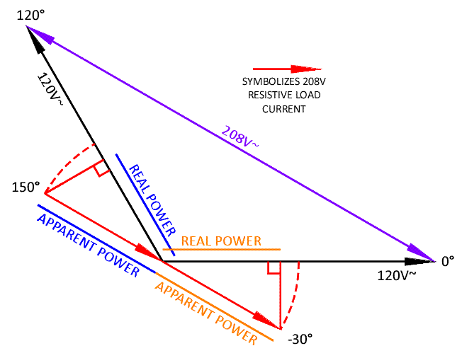
You have to take into consideration the transformer windings which transform and/or derive the voltages, inclusive of the voltage and current phase angles.
 
Yes, with resistive loads... when the applied voltage is supplied by two coupled, yet out-of-phase voltage sources.
Calculate it out and you'll see that each winding utilized provides exactly half of the total real power.
You seem to have a propensity to complicate the point.
Your vector diagram showing the relationship between L-L and L-N is fine.
But then you bisect the 120V vectors.
There is no basis for doing so.
The 208V restive load current is in phase with the 208V.
The relative phase angles of the other voltages has no bearing on that.

I didn't bisect the 120V vectors. I drew two representative 208V resistive-load current vectors that meet at zero volts. These vectors have the same angle as the applied voltage, i.e. 208V. They have no magnitude because I/we have yet to assign one, but yet they appear to have a magnitude simply because one cannot draw a vector without magnitude :)

Yes, they do.

Let's expand on the initial example. Let's say the 208V resistive load draws 20A. How much power is that... 4160VA and 4160W. This also means you have 20A current passing through each of the two connected windings. How much power, in both watts and volt-amperes, is supplied by each of the two windings?
 
Last edited:
I didn't bisect the 120V vectors. I drew two representative 208V resistive-load current vectors that meet at zero volts. These vectors have the same angle as the applied voltage, i.e. 208V. They have no magnitude because I/we have yet to assign one, but yet they appear to have a magnitude simply because one cannot draw a vector without magnitude :)

Yes, they do.

Let's expand on the initial example. Let's say the 208V resistive load draws 20A. How much power is that... 4160VA and 4160W. This also means you have 20A current passing through each of the two connected windings. How much power, in both watts and volt-amperes, is supplied by each of the two windings?
OK. Assume the ?-n voltages on your diagram are:

Va = 120V@0? and Vc = 120V@120?

Current from ?a to ?c is 20A@-30? and flows out of ?a and into ?c
Ia = 20A@-30?
Current flowing out of ?c is 180? from current flowing into ?c
Ic = 20A@150?

Apparent power by phase:
Sa = |Va|?|Ia| = 2400VA
Sc = |Vc|?|Ic| = 2400VA
Stotal = 4800VA

Reactive power by phase:
Qa = |Va|?|Ia|?sin(0? - (-30?)) = 1200var
Qc = |Vc|?|Ic|?sin(120? - 150?) = -1200var
Qtotal = 0var

Real power by phase:
Pa = |Va|?|Ia|?cos(0? - (-30?)) = 2080W
Pc = |Vc|?|Ic|?cos(120? - 150?) = 2080W
Ptotal = 4160W

Note that 20A?208V = 4160W

Even though total reactive power = 0kvar, the overall power factor is:
Ptotal/Stotal = 0.866 = 86.6%
You are correct, saying the power factor is 100% is misleading.:mad:
 
Let's expand on the initial example. Let's say the 208V resistive load draws 20A. How much power is that... 4160VA and 4160W. This also means you have 20A current passing through each of the two connected windings. How much power, in both watts and volt-amperes, is supplied by each of the two windings?
The current in the 208V resistive load is in phase with the voltage applied to it, regardless of how that voltage is derived. It is thus a unity power factor load.
That the arrangement maybe doesn't make best use of the kVA rating of the supply transformer is a different matter.
 
The current in the 208V resistive load is in phase with the voltage applied to it, regardless of how that voltage is derived. It is thus a unity power factor load.
That the arrangement maybe doesn't make best use of the kVA rating of the supply transformer is a different matter.

The major reason for even taking the power factor of loads into consideration is to determine how it affects their power source(s). Loads "could care less" what their power factor is, so long as they are not "starved". Therefore IMO, it is actually not a different matter, but THE matter.
 
Deja vu:

Deja vu:

OK. Assume the ?-n voltages on your diagram are:

Va = 120V@0? and Vc = 120V@120?

Current from ?a to ?c is 20A@-30? and flows out of ?a and into ?c
Ia = 20A@-30?
Current flowing out of ?c is 180? from current flowing into ?c
Ic = 20A@150?

Apparent power by phase:
Sa = |Va|?|Ia| = 2400VA
Sc = |Vc|?|Ic| = 2400VA
Stotal = 4800VA

Reactive power by phase:
Qa = |Va|?|Ia|?sin(0? - (-30?)) = 1200var
Qc = |Vc|?|Ic|?sin(120? - 150?) = -1200var
Qtotal = 0var

Real power by phase:
Pa = |Va|?|Ia|?cos(0? - (-30?)) = 2080W
Pc = |Vc|?|Ic|?cos(120? - 150?) = 2080W
Ptotal = 4160W

Note that 20A?208V = 4160W

Even though total reactive power = 0kvar, the overall power factor is:
Ptotal/Stotal = 0.866 = 86.6%
You are correct, saying the power factor is 100% is misleading.:mad:

This argument has been hashed around ad nauseum in the thread about the infamous Oregon Fudge Factor which indeed does have a technical basis. In this unbalanced case, one could overload the transformers by considering only the L-L load.
 
The major reason for even taking the power factor of loads into consideration is to determine how it affects their power source(s).
Sources and distribution.
The power factor of the load you mentioned in post #49 is unity.
Take for example a single resistive-only 1? 208V load on a 208Y/120 system. The current of said load will be 30? out-of-phase with the applied voltage (i.e. Line to Neutral, that of the windings), resulting in a power factor of .87.
Sure, the current in such a load out of phase with both of the L-N voltages but not out of phase with the applied 208V L-L, thus the load is unity PF. Not 0.866.
 
Sources and distribution.
The power factor of the load you mentioned in post #49 is unity.

The power factor of the load on the system is not unity. That is the whole point of the discussion.

Sure, the current in such a load out of phase with both of the L-N voltages but not out of phase with the applied 208V L-L, thus the load is unity PF. Not 0.866.

Applied voltage is a matter of perspective and reference thereof...

V = 120@0? ? 120@120? = 208@-30?

Whichever perspective it is looked upon, there is no denying the transformer windings are part of the circuit and the discussion would be incomplete from the perspective of voltage applied from nothingness :wink:
 
The power factor of the load on the system is not unity. That is the whole point of the discussion.
My response was based on your comment about the load:
The current of said load will be 30? out-of-phase with the applied voltage
Being a resistive load, there is no phase shift between the voltage applied to it and the current in it.
The transformer is rated in kVA - essentially a current rating.
For some applications, the primary and secondaries have different ratings.
Anyway, I think the topic has been done to death.
 
The power factor of the resistive load is unity.

The power factor placed on the _entire_ transformer secondary is unity.

The power factor placed on an individual coil of the transformer secondary coils is 0.866.

Another way of looking at it is that each transformer coil sees a 'load' that consists of the resistive load in series with the _other_ transformer coil. This composite load does not have a unity power factor.

-Jon
 
The power factor placed on the _entire_ transformer secondary is unity.
What (watt?:-?) is the real power (W) on the transformer? 4160W
What is the total apparent power (VA) on the transformer? 4800 VA
The definition of power factor is the ratio of real power to apparent power. Power factor = 4160/4800 = 0.867
 
Status
Not open for further replies.
Top