EMF Worries

Status
Not open for further replies.

Ravenvalor

Senior Member
I've got a customer who is obsessing over possible EMFs in her home. Is this something that she should be concerned about or is it just another scam industry like the electromagnetic ballast and compact fluorescent lamp industries? For starts, she wants me to remove all of the dimmers in her home. I want my customers to be safe but I don't want them getting ripped off by someone with a gauss meter. My minute understanding of EMFs relating to health issues is that the field is small (6" - 12" max). Any help with this issue would be appreciated.

Thank you,
Jim
 

Dennis Alwon

Moderator
Staff member
Location
Chapel Hill, NC
Occupation
Retired Electrical Contractor
Well there is or has been evidence linked childhood lukemia to EMF's. However, I believe the studies were a bit shaky. Perswonally I would try and eliminate them if I had them.

You can a cheap gaussmeter ($100-$200) and make a little money from it. There are basically 3 things that cause excessive emf's in a home.
 

Dennis Alwon

Moderator
Staff member
Location
Chapel Hill, NC
Occupation
Retired Electrical Contractor
Business has been very slow and the boys have been working anywhere from 3-5 days. I must be nuts because I have been paying them for the 5 days. :)

Things are picking up and I can see lots of work coming up in the next few weeks.

The three common problems I see are:

1) If the ground and neutral touch each other after the load then you will see a spike in emf's

2) If the neutral wire is not run with the hot wire-- an example is a 3 way switch where the electrician runs a 2 wire between 3-way switches and picks up the neutral in one box and the feed in the other 3-way box

3} If the neutrals from 2 different branch circuits are tied together past the load. This often happens in a 2 gang box with 2- 3way switches that are fed from 2 circuits, In the 2 gang the EC decides to tie all the neutrals together.

Good luck
 

geerhed

Member
Location
Your six.
Well there is or has been evidence linked childhood lukemia to EMF's. However, I believe the studies were a bit shaky. Perswonally I would try and eliminate them if I had them.

You can a cheap gaussmeter ($100-$200) and make a little money from it. There are basically 3 things that cause excessive emf's in a home.

Hi Dennis,

What would your criteria for "excessive" be?
 

geerhed

Member
Location
Your six.
I've got a customer who is obsessing over possible EMFs in her home. Is this something that she should be concerned about or is it just another scam industry like the electromagnetic ballast and compact fluorescent lamp industries? For starts, she wants me to remove all of the dimmers in her home. I want my customers to be safe but I don't want them getting ripped off by someone with a gauss meter. My minute understanding of EMFs relating to health issues is that the field is small (6" - 12" max). Any help with this issue would be appreciated.

Thank you,
Jim

Jim,

EMF exposure is primarily a hazard of the workplace, not the home. I'm not sure why your customer is worried about the dimmers in particular, but you have two choices:

1.) inform her of the essentially non-issue EMF in the home is to most (I'm sure there is always an exception somewhere), or

2.) do the work she requests.

I cases like these if the work is done, I would only charge the Ignoramous rate (minimum allowed by conscience). YMMV.
 

Ravenvalor

Senior Member
The three common problems I see are:

1) If the ground and neutral touch each other after the load then you will see a spike in emf's

2) If the neutral wire is not run with the hot wire-- an example is a 3 way switch where the electrician runs a 2 wire between 3-way switches and picks up the neutral in one box and the feed in the other 3-way box

3} If the neutrals from 2 different branch circuits are tied together past the load. This often happens in a 2 gang box with 2- 3way switches that are fed from 2 circuits, In the 2 gang the EC decides to tie all the neutrals together.

Good luck

Hi Dennis,

Can I put in a 3way switching system where the power feed and the switchleg are both in the same box? The other switch is fed with one 3-wire.

Thanks,
Jim
 

kwired

Electron manager
Location
NE Nebraska
Business has been very slow and the boys have been working anywhere from 3-5 days. I must be nuts because I have been paying them for the 5 days. :)

Things are picking up and I can see lots of work coming up in the next few weeks.

The three common problems I see are:

1) If the ground and neutral touch each other after the load then you will see a spike in emf's

2) If the neutral wire is not run with the hot wire-- an example is a 3 way switch where the electrician runs a 2 wire between 3-way switches and picks up the neutral in one box and the feed in the other 3-way box

3} If the neutrals from 2 different branch circuits are tied together past the load. This often happens in a 2 gang box with 2- 3way switches that are fed from 2 circuits, In the 2 gang the EC decides to tie all the neutrals together.

Good luck

add to your list knob and tube wiring as it often does not have all conductors of a circuit run in close proximity to each other.
 

kwired

Electron manager
Location
NE Nebraska
Hi Dennis,

Can I put in a 3way switching system where the power feed and the switchleg are both in the same box? The other switch is fed with one 3-wire.

Thanks,
Jim

if current goes out on one conductor and same current comes back on another (or others in the case of multiwire circuits or multi phase circuits) within the same raceway or cable you have done it right.

If you can clamp an ammeter around an entire cable and get a reading then some of the current is returning through a different path, and you will have increased EMF around this cable

or is it just another scam industry like the electromagnetic ballast and compact fluorescent lamp industries?

I wouldn't say these are scam industries, there are people who use these devices for scams but there are many places where they are completely acceptable or the right thing.

Any product or service can be used for scam salesmen.
 

Ravenvalor

Senior Member
electronic ballasts & compact fluorescent lamps

electronic ballasts & compact fluorescent lamps

I wouldn't say these are scam industries, there are people who use these devices for scams but there are many places where they are completely acceptable or the right thing.

Any product or service can be used for scam salesmen.

A lot of money has been spent (wasted) replacing electronic ballasts.
Compact fluorescent lamps output less light, use more electricity & do not last as long as they advertise.

I admit that I install both, but not before disclosing their problems to the customer.
 

Chamuit

Grumpy Old Man
Location
Texas
Occupation
Electrician
A lot of money has been spent (wasted) replacing electronic ballasts.
Compact fluorescent lamps output less light, use more electricity & do not last as long as they advertise.

I admit that I install both, but not before disclosing their problems to the customer.

Do you have empirical data for this assertion? I hate CFLs.
 

Ravenvalor

Senior Member
data

data

Do you have empirical data for this assertion? I hate CFLs.

The actual power consumption is stamped on the lamp in Ma. Multiply the Ma by the stamped voltage and you always get a higher wattage than the stamped wattage.

My customer's son did a science project study on the light output and the life span. both showed less light output and less life span than advertised.

I use them in hard to reach areas or where they run for long periods of time.
 

gar

Senior Member
Location
Ann Arbor, Michigan
Occupation
EE
100425-2105 EST

Ravenvalor:

I measured a common CFL at 25 W and 44 VA. It is labeled 27 W and 0.45 A. If I scale the 27 and 0.450 to 25, then calculate VA using their labeling gives a higher VA than my measured value. The reason VA does not equal power is that the load current is neither sinusodial or in phase with the voltage. The result is what one should expect.

Get a clamp on Hall device current sensor and connect this to an oscilloscope and observe the current in relationship to the excitation voltage. Sync on a voltage zero crossing. Keep the current sensor well away from the CFL, maybe at least 2 ft. At about 1 ft my Fluke AC/DC probe on the 20 A range starts to see substantial added noise. The current waveform in relation to the sine wave excitation is a vertical step in current at about 55 deg, and droops to zero at about 110 degrees. Peak current is about 0.1 A.

Life of CFLs is dependent on quality of manufacture and how they are applied. I have heard that Energy Star marked bulbs are likely to last longer because there is supposed to be tighter control of design and manufacturing quality. My experience has been fairly good on life of bulbs operated in open free air whether Energy Star or not.

.
 

Ravenvalor

Senior Member
Cfl

Cfl

100425-2105 EST

Ravenvalor:

I measured a common CFL at 25 W and 44 VA. It is labeled 27 W and 0.45 A. If I scale the 27 and 0.450 to 25, then calculate VA using their labeling gives a higher VA than my measured value. The reason VA does not equal power is that the load current is neither sinusodial or in phase with the voltage. The result is what one should expect.

Get a clamp on Hall device current sensor and connect this to an oscilloscope and observe the current in relationship to the excitation voltage. Sync on a voltage zero crossing. Keep the current sensor well away from the CFL, maybe at least 2 ft. At about 1 ft my Fluke AC/DC probe on the 20 A range starts to see substantial added noise. The current waveform in relation to the sine wave excitation is a vertical step in current at about 55 deg, and droops to zero at about 110 degrees. Peak current is about 0.1 A.

Life of CFLs is dependent on quality of manufacture and how they are applied. I have heard that Energy Star marked bulbs are likely to last longer because there is supposed to be tighter control of design and manufacturing quality. My experience has been fairly good on life of bulbs operated in open free air whether Energy Star or not.

.

Thanks for the lesson gar, I will not speak so badly about them.
All this cfl noise you talk about, is this why they won't run on electronic timers like the "Intermatic EJ500"

Jim
 

gar

Senior Member
Location
Ann Arbor, Michigan
Occupation
EE
100428-0647 EST

Ravenvalor:

Of a group of 6 GE CFLs with Energy Star labels that I bought on a special deal 1 was was non-functional on receipt.

Why does a "Intermatic EJ500" not work with CFLs? I do not know.

My conjecture is that if this is a two wire device, meaning it is in series with one lead to the load, then there is not enough current thru the load to power the timer.

On the other hand, if the timer is a three wire device and uses a Triac output, then there may not be enough holding current to keep the Triac on. I did try an OAC5 solid-state relay, Triac output, with both a GE 13 W and a nuivision 27 W and both were switchable.

The CFLs have a bridge rectifier followed by a filter capacitor input. Using a Fluke 27 on ohms you see an initial value that then increases to near infinity. This is what you expect from the bridge rectifier and filter.

You need to study what is inside the EJ500 to see why it does not work.

You could experiment with a 15 W incandescent in parallel with the CFL and see if this works. Then in place of the 15 W try higher resistances and see where failure occurs. A 1000 ohms at 120 V will require a 20 W resistor, 5000 or 5600 ohms 5 W, and 10,000 ohms 2 W.

The magnetic field noise is not the reason.

.
 
Last edited:

ELA

Senior Member
Occupation
Electrical Test Engineer
100425-2105 EST


Get a clamp on Hall device current sensor and connect this to an oscilloscope and observe the current in relationship to the excitation voltage. Sync on a voltage zero crossing. Keep the current sensor well away from the CFL, maybe at least 2 ft. At about 1 ft my Fluke AC/DC probe on the 20 A range starts to see substantial added noise. The current waveform in relation to the sine wave excitation is a vertical step in current at about 55 deg, and droops to zero at about 110 degrees. Peak current is about 0.1 A.

.

Gar,
Did you mean a peak of 1.0 amps?
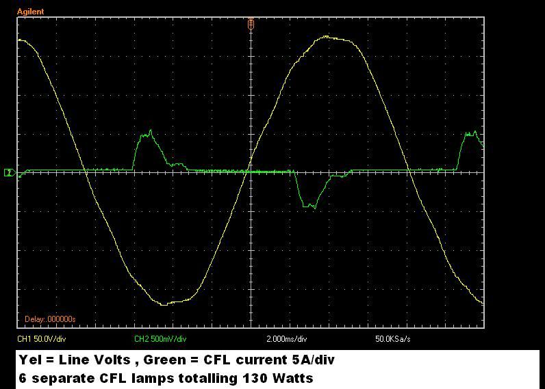
Here is a picture I posted recently in another thread that may help Ravenvalor visualize your description. I have measured many CFLs and they very consistently show a ~ 1 amp peak. Very short duration at 1 amp.
Note the scope trace is 6 bulbs in parallel and so the current "lump" is a combination of several slightly out of phase current waveforms.

ACline-120W6CFLs_50V_div_5A_Div.jpg
 

gar

Senior Member
Location
Ann Arbor, Michigan
Occupation
EE
100427-1224 EST

ELA:

Yes 1.0 A is what I meant. It would be pretty hard to get a 0.4 RMS current from a waveform with only a peak of 0.1 A. I just reran the test to verify and it was 1 A. The measured RMS current is 0.35 . This illustrates why proofreading and double checking are important and one can not do these well by themselves.

.
 
Status
Not open for further replies.
Top