GFCI's do not need an EGC (moved from another thread)

Status
Not open for further replies.
mivey said:
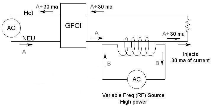
Injection sounded like crossman's phrase "a hypodermic syringe injects a drug into the body", not adding to the circuit. Is this what you are saying you do?:

Currentinjecthuh.jpg

No more like this:

http://www.ets-lindgren.com/manuals/95236-1.pdf
 
mivey said:
Injection sounded like crossman's phrase "a hypodermic syringe injects a drug into the body", not adding to the circuit. Is this what you are saying you do?:

Currentinjecthuh.jpg

The 30ma numbers need to continue the rest of the way around the circuit to be accurate.
 
gar said:
Steady state the DC component will be removed by the current transformer.

Damn. This is embarassing!

I am having trouble grasping the situation. And I am usually a halfway intelligent person. Gar, thanks for replying and giving me pause to think on this. Right now I am legitimately confused.:confused:

Please help correct my thinking here. I fully understand that pure DC current in a xfmr primary can't induce a voltage into the secondary. But a pulsating DC can be transformed. In the sine wave diagram I posted, I was looking at the 2 peaks, and seeing that one wave had more current than the other, so there would be a net magnetic field at that point, which would produce a voltage in the GFCI CT. But upon further thought, I can't just look at that point in time, I have to figure out what is happening to the net change of flux in the CT. I am having a mental block and can't decipher how to picture it in my mnd.

A quick question. If I have an AC current, and add a DC current which elevates the AC sine wave completely above the zero axis so that the current is always flowing in the same direction (although still varying in magnitude as the sine wave), and then run that through a xfmr, the secondary only produces a standard AC wave centered vertically on the zero axis. Is that correct?
 
080722-2228 EST

crossman:

Steady state there will only be the AC component at the transformer output. But there is a transient component in the secondary following the turn on of the voltage or current in the primary. This may produce a damped ringing in the secondary if it is a high-Q circuit, or just an exponentially decaying pulse.

Take a small transformer and apply a DC voltage to the input for a short time and observe the output with an oscilloscope. Trigger the scope from the step rise of the input to the primary.

.
 
gar said:
Steady state there will only be the AC component at the transformer output.

man, I knew that, but it slipped past me on this one. Thanks!

gar said:
But there is a transient component in the secondary following the turn on of the voltage or current in the primary.

Understood. Like the points/coil of an older generation combustion engine.
 
crossman said:
A quick question. If I have an AC current, and add a DC current which elevates the AC sine wave completely above the zero axis so that the current is always flowing in the same direction (although still varying in magnitude as the sine wave), and then run that through a xfmr, the secondary only produces a standard AC wave centered vertically on the zero axis. Is that correct?
That is correct. You'd have an AC wave with a DC offset. The transformer would effectively "filter out" the DC, but would have issues with heat and saturation, causing a gross reduction in ampacity.
 
crossman said:
I fully understand that pure DC current in a xfmr primary can't induce a voltage into the secondary. But a pulsating DC can be transformed. In the sine wave diagram I posted, I was looking at the 2 peaks, and seeing that one wave had more current than the other, so there would be a net magnetic field at that point, which would produce a voltage in the GFCI CT.
First of all, a 'pulsating-DC' (or a square-wave) can be used to supply a transformer, but like I mentioned above, it's a bit less efficient. The old-fashioned 60Hz inverters used a push-pull inverter circuit on the primary, and the output was far from being a sine wave.

More modern ones use high frequencies to step the 12v up to 120v, and then the 60Hz output is 'synthesized' and is what's called a 'modified sine wave.' It's still a square wave, but spends a bit of time at zero volts between positive and negative peaks.

A one-shot energization and de-energization produces the most energy when the magnetic field collapses upon de-energization. This is how the basic automotive ignition systems work. The high voltage spike is generated when the ignition points open.

I think your experiment with DC didn't work because your pulse of current was of too short a duration. You could always put a 6v battery in series with the 6v transformer, but that would simply tell you whether a DC offset affects the GFCI's operation, which I doubt.
 
LarryFine said:
That is correct. You'd have an AC wave with a DC offset. The transformer would effectively "filter out" the DC, but would have issues with heat and saturation, causing a gross reduction in ampacity.

Larry, I'm not sure I catch what you mean. If the primary input is a sine wave with a large DC offset, so that the sine wave is totally above the horizontal axis, then the secondary output will have no DC offset at all, right? In other words, it will be a "normal" sine wave current with two quadrants above the zero axis and two quadrants below the zero axis? (with the losses that you mentioned.)
 
crossman said:
Larry, I'm not sure I catch what you mean.
You do. :smile:

Yes, the DC will flow in the primary, and create heat magnetizing the transformer core, but will be invisible at the output.

By the way, a series capacitor will do the same thing; charge to the DC-component's level, and pass AC at the same time.
 
Last edited:
LarryFine said:
You do. :smile:

Yes, the DC will flow in the primary, and create heat magnetizing the transformer core, but will be invisible at the output.

By the way, a series capacitor will do the same thing; charge to the DC-component's level, and pass AC at the same time.

Thank you for helping clear it up for me. :smile:
 
LarryFine said:
First of all, a 'pulsating-DC' (or a square-wave) can be used to supply a transformer, but like I mentioned above, it's a bit less efficient. The old-fashioned 60Hz inverters used a push-pull inverter circuit on the primary, and the output was far from being a sine wave.

More modern ones use high frequencies to step the 12v up to 120v, and then the 60Hz output is 'synthesized' and is what's called a 'modified sine wave.' It's still a square wave, but spends a bit of time at zero volts between positive and negative peaks.

A one-shot energization and de-energization produces the most energy when the magnetic field collapses upon de-energization. This is how the basic automotive ignition systems work. The high voltage spike is generated when the ignition points open.

I think your experiment with DC didn't work because your pulse of current was of too short a duration. You could always put a 6v battery in series with the 6v transformer, but that would simply tell you whether a DC offset affects the GFCI's operation, which I doubt.


Modified as in:


modsine.jpg
 
gar said:
With a single closed loop the current in every part has to be the same. Thus, there is no imbalance from your injected current.
LarryFine said:
The 30ma numbers need to continue the rest of the way around the circuit to be accurate.
LOL. Thanks for the tips.

Michael understands how it is supposed to look. Michael did not understand how someone was going to "inject" 30 mA of current that did not pass through the coil in both directions in the GFCI without some kind of shunt around the coil.
 
080723-1148 EST

A GFCI will not prevent a shock, nor will it trip because I put one finger on the hot output lead and a finger on the other hand on the earth. For someone else it might trip, or for me under non-normal conditions.

My usual resistance from a finger on one hand to a finger on the other hand is 300,000 to 500,000 ohms. At 120 V this is 0.4 to 0.24 MA. This is way below the trip level of the GFCI.

At 120 V to trip at 5 MA the resistance thru me must be below 24,000 ohms.

However, if I am holding a metal housing electric drill with a working EGC system, then an internal short less than about 24,000 ohms from the hot line to the drill motor housing should trip within 7 seconds. If this was a dead short then the housing voltage will rise to about 60 V RMS (85 V peak) until the GFCI trips. For the dead short the GFCI may take up to 16 MS to trip, but most likely within 8 MS. I will get a shock. I have not run a trip time measurement.

.
 
gar said:
080723-1148 EST

A GFCI will not prevent a shock, nor will it trip because I put one finger on the hot output lead and a finger on the other hand on the earth. For someone else it might trip, or for me under non-normal conditions.

My usual resistance from a finger on one hand to a finger on the other hand is 300,000 to 500,000 ohms. At 120 V this is 0.4 to 0.24 MA. This is way below the trip level of the GFCI.

At 120 V to trip at 5 MA the resistance thru me must be below 24,000 ohms.

However, if I am holding a metal housing electric drill with a working EGC system, then an internal short less than about 24,000 ohms from the hot line to the drill motor housing should trip within 7 seconds. If this was a dead short then the housing voltage will rise to about 60 V RMS (85 V peak) until the GFCI trips. For the dead short the GFCI may take up to 16 MS to trip, but most likely within 8 MS. I will get a shock. I have not run a trip time measurement.

.
Your resistance values are certainly high. Probably higher than we might expect to normally encounter.

A dry finger touch is 40k-1M. When working, you might be sweating, putting you at 4k-15k for the finger touch, less for a hand touch or "wire pinch" drops to 1/2 to 1/4 of that. The arms and torso add about 1k. Then you have the other finger.

So sweating we are talking about around 10k-30k. This is the kind of level we will probably be talking about while working.

Dry we are talking about 80k to 2M. Probably not typical for a work environment.

Sounds like you are using some dry measurements.

The minimum whole body resistance is thought to be about 500 ohms.

Skin is the big factor. Once the voltage overcomes the skin, you have very little resistance. Voltages of 550 volts can puncture the skin and then you have contact with the low internal resistance, which is hundreds of ohms instead of thousands of ohms.
 
080723-1637 EST

mivey:

Yes I used my dry skin measurements to illustrate that this would not trip the GFCI. Even your sweaty figure of 30,000 ohms at 120 V won't cause a trip.

But your figures are very good because they do correspond with potential electrocution. Your point about breakdown of the skin is very important.

What I primarily wanted to emphasize was that a GFCI does not prevent being shocked, either with or without tripping the GFCI.

.
 
gar said:
My usual resistance from a finger on one hand to a finger on the other hand is 300,000 to 500,000 ohms. At 120 V this is 0.4 to 0.24 MA. This is way below the trip level of the GFCI.
. . . and way below electrocution level.

At 120 V to trip at 5 MA the resistance thru me must be below 24,000 ohms.
What would your resistance need to be for the current to approach dangerous shock-hazard levels?

However, if I am holding a metal housing electric drill with a working EGC system, then an internal short less than about 24,000 ohms from the hot line to the drill motor housing should trip within 7 seconds. If this was a dead short then the housing voltage will rise to about 60 V RMS (85 V peak) until the GFCI trips. For the dead short the GFCI may take up to 16 MS to trip, but most likely within 8 MS. I will get a shock.
This sounds like an argument for EGC's, which nobody claims is undesirable.


If your point is that GFCI's and EGC's are better than just GFCI's, I don't think anyone would argue with you. However, I'll take 8 to 16 ms over 7 seconds any day.
 
080723-1912 EST

Larry:

It definitely argues for GFCIs.

The following reference that I listed at post #62
http://hyperphysics.phy-astr.gsu.edu/hbase/electric/shock.html#c3
provides information on the effects of various current levels. There is no reference relative to time duration.

Another reference
http://www.mex.tuv.com/docs/Effects_of_Electrical_Current_in_Human_Body.pdf

This reference seems to be very good and references original research.
http://www.allaboutcircuits.com/vol_1/chpt_3/11.html

.
 
A GFCI does need a ground in order for the test button on the unit to work. It does not need a ground conductor in order to functon properly under a ground fault condition.
 
jinglis said:
A GFCI does need a ground in order for the test button on the unit to work. It does not need a ground conductor in order to functon properly under a ground fault condition.
No. It does not need a ground for the test button to work.
 
Status
Not open for further replies.
Top