careco1 said:
I have a new detached garage which contains living quarters. We installaed a sub panel fed from the existing service on an existing house. the sub panel is a 125 amp indoor load center containg approx 10 new circuits for the garage and living space fed with a 100 amp feeder. The feeder contains an equipment grounding conductor sized to the overcurrent device protecting the new feeder. The inspector is requiring me to to add 2 ground rods outside the new building and connect them to the grounding bar in the sub panel. He also wants a main breaker for disconnecting means at the new panel. Is this right?
The grounding electrode system is required at the remote building supplied by branch circuits or feeders according to 250.32(A).
The second building requires its own grounding electrode system according to 250.32(A). That is non-trivial to explain. Suffice it to say you need it. If you had a CEE meeting the definition of 250.52(A)(3), you'd have had to bond it too. 250.50 and 250.52 are a starting point for your reading relaxation.
The main breaker is required to be on the inside or outside of the building it serves according to 225.32. No exceptions are likely to apply, unless you are recognized as qualified by the AHJ and you fulfill the requirements of exception 1. Therefore, the inspector is most likely right about requiring it.
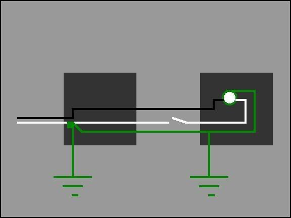
By installing the four-wire system according to 250.32(B)(1) you eliminate the possibility of generating "stray voltage" with your installation by inducing a neutral current paralleled on the GES's of the two buildings through the earth. By following 250.32(B)(1) you are required to NOT bond the grounded conductor and the GES at the second building. This is a good thing. Of course, "stray voltage" will be induced during a ground-fault event, but with proper coordination that should be an ephemeral event - short-lived, even ;-). 250.122 gives the minimum EGC size. There is no rule prohibiting you from using a larger conductor, if you are concerned with ground-fault clearing times.
"And now, ... "
"Hey, Rocky! Watch me pull a rabbit out of my hat!"
"Again?"
"Nuthin' up my sleeve...Presto!"
An open neutral anywhere in the system will result in line-to-line current flow across the 240v on 120v circuits, instead of L-N flow as wanted, and will likely pull the open neutral toward one or the other line depending on several factors related to energized connected loads. This is not a good thing, as it could damage connected loads, but it will NOT cause ground current by itself. If you had an even number of equal-sized incandescent lamps, evenly distributed across the two line legs, and all of them on, and no other 120v loads attached, you probably wouldn't even notice the open neutral, since the lamp loads would act as voltage dividers and you'd have no significant voltage between the open neutral and ground. This is usually not the case, and you end up with a lopsided load. This will result in elevated neutral voltage on the open neutral. If a connected load fails as a consequence of the elevated L-N voltage on its leg and it shorts to its EGC, then you'll have ground current flowing. Again, proper coordination will clear the fault (hopefully sooner than later). You'll have to remedy the open neutral. It's not hard to diagnose; it will usually show up as an unusual N-G voltage at the downstream panel.
"No doubt about it. I've gotta get me another hat!"
"Now here's something you'll *really* like."
Sorry to butt in on a very long discussion; I just thought it would be refreshing to answer the first post in the thread. You may resume the hostilities.
[added 1925] Sorry, Roger. You did answer the question. So did Tom Baker. Please accept my apologies.
Dan