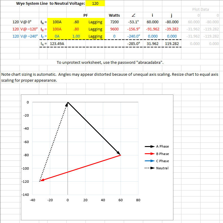
Is this calc right?

Status
Not open for further replies.

mivey

Senior Member
nope
not if converted to rectang

try it:
Re = signed mag x cos (signed ang)
Img = signed mag x sin (signed ang)

that is an issue
probably signing/convention related
I am quite comfortable in my math skills and grasp of concepts so no need to "try" anything. I'm sure you are as well so something is being lost in translation.

The point is that a vector in any quadrant can be resolved into its rectangular coordinates. Adding or subtracting 360 degrees to that vector will give you the same reactangular coordinates again. That is the point Smart$ was making.

Not sure what your point is but I'm thinking I'm getting less interested by the minute unless you get to it. All I have seen is some math and formulas which are going nowhere. I suspect your point has more to do with opinion about something. Not sure.
 

mivey

Senior Member
1&4 are the same, 2&3 are the same. 1&4 are opposite to 2&3 (opposite sign, opposite vector direction: your choice).

1&4 are the same, 2&3 are the same. 1&4 are in diagonally opposite quadrants to 2&3.

nope
not if converted to rectang

try it:
Re = signed mag x cos (signed ang)
Img = signed mag x sin (signed ang)

that is an issue
probably signing/convention related
My error. I did not notice the sign at the beginning as I was focusing on angles. They are all the same.
 

mivey

Senior Member
And they are off and running folks.:)

Odds: min 100+ posts.

Cool thread guys.
Now that I corrected my error, I think I'll stop running.:D

No point in arguing which of two valid conventions is "correct" unless just bored and I have a meeting to make.
 

Ingenieur

Senior Member
Location
Earth
Please let it be the last time.

My convention is 0 = IA + IB + IC + IN. You even said in your prior post, and I quote...

I apply my convention consistently. Live with the fact that you are incorrect. ;)

convention as in rotation, pos or neg seq, angle assignment (0,120,-120 or 0, -120, -240)
but not in the direction of current, voltage drop, power flow, etc.

the angle is not correct
the mag is
 

Smart $

Esteemed Member
Location
Ohio
convention as in rotation, pos or neg seq, angle assignment (0,120,-120 or 0, -120, -240)
but not in the direction of current, voltage drop, power flow, etc.

the angle is not correct
the mag is
Are you disagreeing with using 0 = IA + IB + IC + IN rather than IN = IA + IB + IC or are you saying the angle is wrong for IN? If the former you are contradicting yourself (convention and all). If the latter prove it.

BTW, you should seriously think about what happens when using the formula IN = IA + IB + IC. Say just IA is conducting, IN cannot be in the same direction at the same time. It's a simple circuit. IN + IA must equal 0.
 

Ingenieur

Senior Member
Location
Earth
Are you disagreeing with using 0 = IA + IB + IC + IN rather than IN = IA + IB + IC or are you saying the angle is wrong for IN? If the former you are contradicting yourself (convention and all). If the latter prove it.

BTW, you should seriously think about what happens when using the formula IN = IA + IB + IC. Say just IA is conducting, IN cannot be in the same direction at the same time. It's a simple circuit. IN + IA must equal 0.

angle: it's wrong, plain and simple
not valid: 0 = IA + IB + IC + IN


it's all out there for the reader to arrive at their own conclusion
relax, it's ok to be wrong
 

wwhitney

Senior Member
Location
Berkeley, CA
Occupation
Retired
angle: it's wrong, plain and simple
not valid: 0 = IA+ IB + IC + IN
I haven't followed the argument between you guys very closely, but using the numbers from the first post, google tells me that:

100*e^(2*pi*i*53.1/360) + 100*e^(2*pi*i*156.9/360) + 123.49*e^(2*pi*i*285/360) = 0.02 - 0.08i

which for the purposes at hand is very close to zero, probably within rounding error on the angles.

[Note that I multiplied all the angles by -1 for convenience; this is equivalent to taking the complex conjugate. So with negative angles as in the first post, IA+ IB + IC + IN = 0.02 + 0.08i.]

Cheers, Wayne
 

wwhitney

Senior Member
Location
Berkeley, CA
Occupation
Retired
Shouldn't a lower power factor on one leg actually cause the neutral current to drop- rather than rise?
Getting back to the OP, can a single L-L load cause the currents and line power factors shown in the calculations? Or would it require two different L-N loads?

If the current and line power factors shown in the OP are caused by two different L-N loads, then would swapping the two loads (or swapping the two legs powering the loads) cause the the neutral current to drop? I.e. neutral current is higher than the resistive case when the angle between the current phasors drops below 120 degrees, and lower than the resistive case when the angle exceeds 120 degrees (at least up to 180 degrees). And swapping the two loads would swap between those two cases?

Thanks,
Wayne
 

Smart $

Esteemed Member
Location
Ohio
Getting back to the OP, can a single L-L load cause the currents and line power factors shown in the calculations? Or would it require two different L-N loads?

If the current and line power factors shown in the OP are caused by two different L-N loads, then would swapping the two loads (or swapping the two legs powering the loads) cause the the neutral current to drop? I.e. neutral current is higher than the resistive case when the angle between the current phasors drops below 120 degrees, and lower than the resistive case when the angle exceeds 120 degrees (at least up to 180 degrees). And swapping the two loads would swap between those two cases?

Thanks,
Wayne
Line-to-line loads do not affect neutral current. The currents shown are for line-to-neutral only loads.

Here's the entire picture...

Original%20calc.png


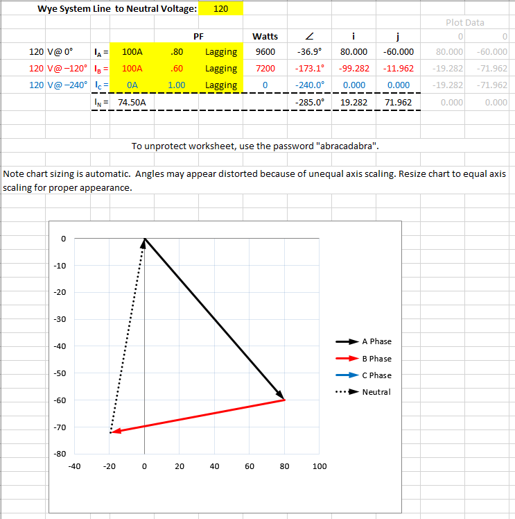
If one swaps the original loads...

Swapped%20calc.png


As you can see, the magnitude of the neutral current is lowered.
 
angle: it's wrong, plain and simple
not valid: 0 = IA + IB + IC + IN


it's all out there for the reader to arrive at their own conclusion
relax, it's ok to be wrong
Your being intentionally obtuse. I sum all currents to zero. If you understand KCL both methods make equal sense. All that matters is that the sum of currents entering a node equal the currents exiting the node. I feel as engineers we should learn concepts rather than marry ourselves to formulas.
 

Smart $

Esteemed Member
Location
Ohio
Your being intentionally obtuse. I sum all currents to zero. If you understand KCL both methods make equal sense. All that matters is that the sum of currents entering a node equal the currents exiting the node. I feel as engineers we should learn concepts rather than marry ourselves to formulas.
:thumbsup::thumbsup::thumbsup:
 

Smart $

Esteemed Member
Location
Ohio
...All that matters is that the sum of currents entering a node equal the currents exiting the node. ...
With AC, especially 3Ø, to lump currents entering and exiting a node together on opposing sides of the equal sign is going to amount to flipping variables across the equal sign quite often... up to one every 1/180th second. :D
 

Ingenieur

Senior Member
Location
Earth
Your being intentionally obtuse. I sum all currents to zero. If you understand KCL both methods make equal sense. All that matters is that the sum of currents entering a node equal the currents exiting the node. I feel as engineers we should learn concepts rather than marry ourselves to formulas.

accurate, not obtuse weth that means

if you understand Kirchhoff's first and second law you know them as:
the standard method and KCL states all entering = those leaving
conservation of energy
every text I've ever seen: Ia + Ib + Ic = In

the facts do not care how we feel :happyno:
the formulas represent the concepts, misapplied indicates understanding of neither
you can have your own opinions, but not your own facts, you can't rewrite the basic laws to fit your understanding
 
Status
Not open for further replies.
Top