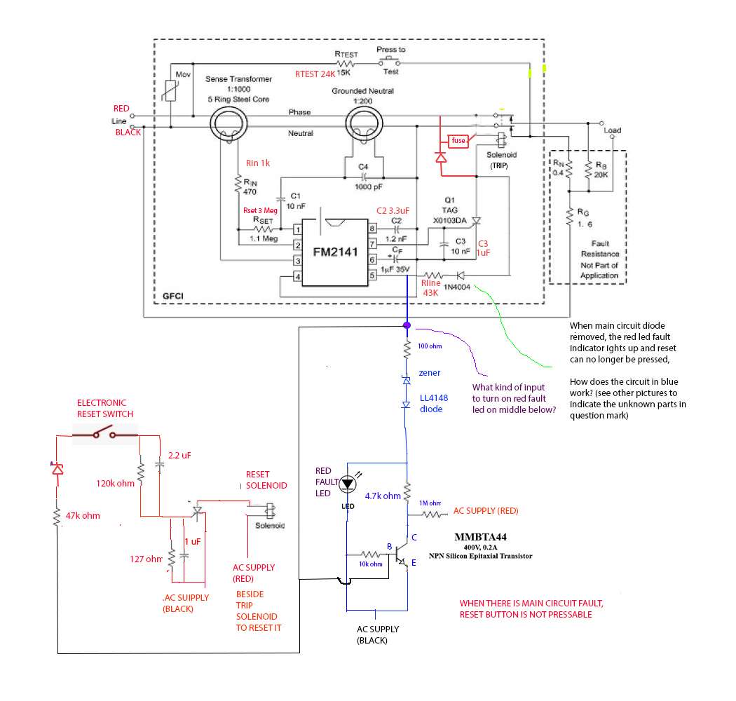
Leviton GFCI nuisance tripping and circuit analysis

Status
Not open for further replies.
190119-0850 EST

tersh:

The PNP is only rated 65 V. Can't put PNP, 4.7k, and LED in series across an AC 240 V line. Things will blow up. Not one of the components could tolerate this. Both the forward and reverse directions are a disaster.

.

Are all PNP rated 65V? Someone at stack exchange identify the tiny transistor as PNP. Maybe another model of PNP. Note in the actual pcb picture, you can see the emitter of it (or whatever it is) connected to the AC black line.

Also in the Rline of 43K in series to the diode you asked me to remove. In a brand new PCB. I only measure 12volts in the Rline leading to the violet dot.

Y1Ayj9.jpg


The Reset is connected to the top of the receptacle. It's on the right. The two red wire is connected to the button. In the left Test button, one is connected to load line, while there is a resistor going to outside line (as is how Test button) connected.

I can easily connect the sense coil of the 4th gfci pcb and it will be working but can't be put back in service. And I don't have the skill to look at it furthermore and learn the real source of the transient or current imbalance and how it affects the sense coil and pin 1,2,3. So maybe I can just send it to you along with the water shaded pole motor? I will never use it anymore. I avoid anything above 3mG. And the motor is about 200mG from my brain.
 
190119-0916 EST

tersh:

No matter what the switching device is NPN, PNP, SCR, FET, or mechanical switch, the LED in series with 4.7 K can not tolerate a source voltage of 340 V peak in either polarity, nor the resistor.

47 V / 4.7 k is 10 mA which is very bright for todays LEDs used as a pilot light. More likely voltage is down in the 10 V range for a 4.7 k series resistor.

Use an ohmmeter to verify where some of those leads go.

.


Actually I was thinking about that too. I could light up the red led by simply putting my multimeter terminals to them. But in the actual circuit. The negative or pin 1 of the red led is really connected to the AC terminal at bottom. While pin 2 is connected just as I indicated in the circuit.

cs2hP2.jpg


This is back side again:

JesXN6.jpg


This is the datasheet of the 400v NPN

http://www.secosgmbh.com/datasheet/products/SSMPTransistor/SOT-23/MMBTA44.pdf

This is the NPN symbol with the arrow reversed: I'll quadle check everything tomorrow. Many thanks.

Qe59A2.jpg
 
190119-1059 EST

tersh:

I like the NPN as a more likely device. The 10k base to emitter is OK. Emitter going to AC power black seems OK, that is the common for the IC chip.

Something wrong with LED location, orientation, and it can not go to the AC power red with with just 4.7k current limiting.

In proper orientation and with 4.7k and 10 V would be OK.

.
 
100119-1124 EST

Something wrong. My last post does not show up.

By submitting this post my previous one now shows.

Addition to previous post --- there must be some current limiting going to the transistor base. The rede line to the base requires some adequate resistance.

.
 
Last edited:
190119-1059 EST

tersh:

I like the NPN as a more likely device. The 10k base to emitter is OK. Emitter going to AC power black seems OK, that is the common for the IC chip.

Something wrong with LED location, orientation, and it can not go to the AC power red with with just 4.7k current limiting.

In proper orientation and with 4.7k and 10 V would be OK.

.

I have so many subjects about transistor computations back in college. It's what we were taught from the start, but after 25 years of not looking at them. I have forgotten but it's easy if I'd see them again.

I measured only 1.4v in the red LED when it's lighting up from removed diode (or disconnected). But note even if the LED is has just 4.7k current limit. There must be something inside pin 5 where it has more resistance. Then by divider action, the voltage across the 4.7k must be much smaller.

What's really weird is that when the SCR from pin 7 was removed. The red led lights up even when the diode (you said to remove) and resistor is still connected to the AC red. How can it know when the SCR was removed?

The voltage between pin 5 and resistor Rline (43k) just 12 volts. So there must be voltage divider occurring right at pin 5, should be some high resistance inside the chip itself. What do you think? I have double checked again and again and the led connection is correct.
 
190119-1911 EST

tersh:

For the most part I would view that most measurements should be relative to IC pin 4 as the reference. This is also the same as the black power lead.

The voltage on pin 5 relative to pin 4 should be positive and of some moderately low value. Likely an average value of + 10 to 20 V, and possibly a half sine wave, and possibly clamped by something in the IC, but unlikely. The 47k resistor in combination with the IC current load and/or other load current determines the voltage based on division from a half wave rectified 240 V 60 Hz input.

It appears the reset circuit is totally independent of anything else other than for power from the pin 5 location to trigger the reset SCR.

I believe power from pin 5 of the IC should go to the junction between the diode and the 47k resistor, rather than at the bottom end of the 47k resistor. Then there would be current limiting to the NPN transistor base from the 47k resistor. In other words the 47k belongs to the NPN not the SCR.

.

I reconnected the cut path to the inbalance sense coil. This was after 2 days of constantly switching the shaded pole motor on and off, and it didn't trigger even one time. This is consistent. The same effect can be done by shorting pin 1, 2, 3 (which I had done 4 days ago before cutting the path). So I reconnected the cut path by simply soldering the path a bit so the circuit will be fully working again after I got tired switching the motor on and off without any tripping. After I reconnected. The Test button work again and the motor tripped once in 4 switchings (see earlier youtube video of me doing it in less than 2 minutes and about 7 trippings).

This is how the path is cut. It's near pin 3. If you will see the board layout front and back in earlier post. The path leads directly to the sense coil.

j9tIh4.jpg


OIYN4o.jpg


While mulling about the led puzzle. Let's try to discuss about transients meantime.

1. Can capacitive coupling induce voltage only wire with capacitor.. or even without capacitor?

2. Does it induce voltage in all the wires. In the above case, when the path is cut. If there is induced capacitive coupling voltage in the wire. Can it only enter pin 1 and 2 with pin 3 hanging? The longer path in the pcb is that cooper path from pin 3 to the sense coil (almost 2 inches), I wonder if voltage can be induced there. Let's say it could. If the portion in pin 3 is cut. Can the induced voltage enter the other lines too and sufficient to cause tripping?

3. If the above is so. How does tripping occurs. By directly triggering the SCR or artificially putting current into the wires making pin 1, 2, 3 think it was sensing actual current inbalance in the sense coil?

This is assuming the tripping is caused by transient getting into the wire. And assuming I'm accurate that cutting it eliminate tripping. I had switched the motor about 200 times when all pin 1,2,3 shorted and 200 times when the path is cut. Both eliminated the trips. But in science or engineering. Others have to duplicate it to be believable so let's just assume I was accurate for sake of discussions.

3. If there is induced voltage from capacitive coupling in the wires. Can shorting pin 1, 2, 3 eliminate the induced voltage? If not. Then maybe it's really actual current inbalance?

4. If it is actual current inbalance, how come it never trip on the Siemens 2-pole GFCI breaking with similar 5mA tripping, and how come it can be eliminated by using LC filter on the motor?

5. I put the circuit back to normal to measure the voltage in Rline, diode, pin 5 and I got the readings. I'll report about it after we at least discussed transients. I'm still mulling and checking the circuit how the LED got so low voltage when it's connected 240v in one leg. Thank you.
 
190119-1911 EST

tersh:

For the most part I would view that most measurements should be relative to IC pin 4 as the reference. This is also the same as the black power lead.

The voltage on pin 5 relative to pin 4 should be positive and of some moderately low value. Likely an average value of + 10 to 20 V, and possibly a half sine wave, and possibly clamped by something in the IC, but unlikely. The 47k resistor in combination with the IC current load and/or other load current determines the voltage based on division from a half wave rectified 240 V 60 Hz input.

It appears the reset circuit is totally independent of anything else other than for power from the pin 5 location to trigger the reset SCR.

I believe power from pin 5 of the IC should go to the junction between the diode and the 47k resistor, rather than at the bottom end of the 47k resistor. Then there would be current limiting to the NPN transistor base from the 47k resistor. In other words the 47k belongs to the NPN not the SCR.

.

I have traced the mistakes about the LED. In the following circuit trace, the LED terminal is clearly labeled N, so it should go to the black which is N, and using continuity test confirms it. It's not really connected to the Hot red line.

ey1esW.jpg


So the circuit diagram is reflecting the corrections:

QM9Okq.jpg


What do you think about the above, the LED is not directly connected to the red line, but only the black line.

I made some measurements. First with a normal working pcb and with one where pin 1 was cut destroying the SCR (it seems without Rset, pin 7 fires with continuously cycle, let's discuss this some other time)

In the normal pcb with no red led on, pin 5 has ac of 12.2v and dc of 15.4v
In the fried SCR pcb with red led on, pin 5 has ac of 29v and no dc voltage! why?

for the working pcb Resistor going to pin 5, the voltage is 119v ac, 94.4 dc
for the fried SCR pcb, Resistor going to pin 5, the voltage is 115v ac, 95v dc
(it's almost the same between them)

for the working pcb, diode going to pin 5, the voltage is 113v ac, 108v dc
for the fried SCR pcb, diode going to pin 5, the voltage is 113v ac, 90v dc

for both, the 100ohm going to pin 5 is about 8.4 volts

for the bad pcb, the 4.7kohm parallel to led measures 10.5v ac, 7.95v dc
for the good pcb, the 4.7kohm parallel to led measures 13.8 ac, no dc!

when I mentioned bad pcb (or one with fried SCR), the red led turns on continuously. Never on the good pcb.

From the above. Any clue what triggers or turn on the red led?? Also note that whenever the red led is on, you can never reset the solenoid. So the reset circuit is connected to whether the red led is one or not.

(please don't miss my last message about the transient analysis, thanks).
 
190119-2347 EST

tersh:

A typical LED in the forward diode direction, direction in which light is produced, has a voltage drop of 1 to 2 V before current is so high as to destroy the LED. If you were to drive a single LED from 240 and wanted to hold the currnet to about 10 mA, then the series R needs to be greater than 24000 ohms. Further you would need a shunt diode in parallel with the LED, and reverse biased, to conduct when the LED was back biased to prevent excessive peak inverse voltage (PIV) on the LED.

Q1 --- Any two conductive elements spaced by an insulator form a capacitor. Two adjacent wires form a capacitor, but of a small value. Two wires in a CAT-5 cable have about 15 pfd per foot.

Q2 --- Longer wires produce greater capacitance. Cutting a wire will reduce capacitance in an otherwise un-modified layout.

Q3 --- If pins 1, 2, and 3 are shorted together, then the voltage between them is essentially 0. Thus, capacitive coupling to the wires would not put a signal into the chip. If a signal between 123 together and 4 was present, and if the chip was sensitive to this as a signal, then tripping from capacitive coupling could occur. But I think 1,2,3 are some form of differential amplifier input.

Q4 --- May or may not be a current imbalance. A different time constant for the inverse time function could make a difference between different manufacturers.

Q5 --- See my first comment before Q1. Your circuit that includes the LED can not be correct as you have drawn it. See my earlier post.

.
 
I have traced the mistakes about the LED. In the following circuit trace, the LED terminal is clearly labeled N, so it should go to the black which is N, and using continuity test confirms it. It's not really connected to the Hot red line.

ey1esW.jpg


So the circuit diagram is reflecting the corrections:

QM9Okq.jpg


What do you think about the above, the LED is not directly connected to the red line, but only the black line.

I made some measurements. First with a normal working pcb and with one where pin 1 was cut destroying the SCR (it seems without Rset, pin 7 fires with continuously cycle, let's discuss this some other time)

In the normal pcb with no red led on, pin 5 has ac of 12.2v and dc of 15.4v
In the fried SCR pcb with red led on, pin 5 has ac of 29v and no dc voltage! why?

for the working pcb Resistor going to pin 5, the voltage is 119v ac, 94.4 dc
for the fried SCR pcb, Resistor going to pin 5, the voltage is 115v ac, 95v dc
(it's almost the same between them)

for the working pcb, diode going to pin 5, the voltage is 113v ac, 108v dc
for the fried SCR pcb, diode going to pin 5, the voltage is 113v ac, 90v dc

for both, the 100ohm going to pin 5 is about 8.4 volts

for the bad pcb, the 4.7kohm parallel to led measures 10.5v ac, 7.95v dc
for the good pcb, the 4.7kohm parallel to led measures 13.8 ac, no dc!

when I mentioned bad pcb (or one with fried SCR), the red led turns on continuously. Never on the good pcb.

From the above. Any clue what triggers or turn on the red led?? Also note that whenever the red led is on, you can never reset the solenoid. So the reset circuit is connected to whether the red led is one or not.

(please don't miss my last message about the transient analysis, thanks).

Btw. The 1 meg ohm resistor is from.collector to ac line red. Not black. I put red in original diagram but when i changed the led leg to black ac line. I moved the 1M ohm to black as well. It should be red..thanks.


Havent traced a circuit even in college. First time. Sorry.
 
Last edited:
7i3hHP.jpg


gar and other electronics experts, above is the clearest diagram so far...

but note during normal operation, the red led never light up. only during fault. What do you think
should be in the violet dot so the red led would turn on?

again the measurements in my message #170

I made some measurements. First with a normal working pcb and with one where pin 1 was cut destroying the SCR (it seems without Rset, pin 7 fires with continuously cycle, let's discuss this some other time)

In the normal pcb with no red led on, pin 5 has ac of 12.2v and dc of 15.4v
In the fried SCR pcb with red led on, pin 5 has ac of 29v and no dc voltage! why?

for the working pcb Resistor going to pin 5, the voltage is 119v ac, 94.4 dc
for the fried SCR pcb, Resistor going to pin 5, the voltage is 115v ac, 95v dc
(it's almost the same between them)

for the working pcb, diode going to pin 5, the voltage is 113v ac, 108v dc
for the fried SCR pcb, diode going to pin 5, the voltage is 113v ac, 90v dc

for both, the 100ohm going to pin 5 is about 8.4 volts

for the bad pcb, the 4.7kohm parallel to led measures 10.5v ac, 7.95v dc
for the good pcb, the 4.7kohm parallel to led measures 13.8 ac, no dc!

when I mentioned bad pcb (or one with fried SCR), the red led turns on continuously. Never on the good pcb.

From the above. Any clue what triggers or turn on the red led?? Also note that whenever the red led is on, you can never reset the solenoid. So the reset circuit is connected to whether the red led is one or not.
 
A repeat- you need to download and learn to use one of the fea circuit analysis tools such as LTSpice or Orcad student version PSpice.

Don't expect someone else to analyze incomplete schematics provided piecemeal.

Include in your model the effects of opening one line of the SP motor that leave one line thru the CTs with a current flowing, compare to the delay times of the trip circuits,

etc.
 
7i3hHP.jpg


gar and other electronics experts, above is the clearest diagram so far...

but note during normal operation, the red led never light up. only during fault. What do you think
should be in the violet dot so the red led would turn on?

again the measurements in my message #170

I made some measurements. First with a normal working pcb and with one where pin 1 was cut destroying the SCR (it seems without Rset, pin 7 fires with continuously cycle, let's discuss this some other time)

In the normal pcb with no red led on, pin 5 has ac of 12.2v and dc of 15.4v
In the fried SCR pcb with red led on, pin 5 has ac of 29v and no dc voltage! why?

for the working pcb Resistor going to pin 5, the voltage is 119v ac, 94.4 dc
for the fried SCR pcb, Resistor going to pin 5, the voltage is 115v ac, 95v dc
(it's almost the same between them)

for the working pcb, diode going to pin 5, the voltage is 113v ac, 108v dc
for the fried SCR pcb, diode going to pin 5, the voltage is 113v ac, 90v dc

for both, the 100ohm going to pin 5 is about 8.4 volts

for the bad pcb, the 4.7kohm parallel to led measures 10.5v ac, 7.95v dc
for the good pcb, the 4.7kohm parallel to led measures 13.8 ac, no dc!

when I mentioned bad pcb (or one with fried SCR), the red led turns on continuously. Never on the good pcb.

From the above. Any clue what triggers or turn on the red led?? Also note that whenever the red led is on, you can never reset the solenoid. So the reset circuit is connected to whether the red led is one or not.


gar, when I isolate this circuit (remember I have three pcbs junked).

TwkDiu.jpg


The red led can light up. This first occurred when you told me to remove the main diode to pin 5. I isolate it even further by just having the above circuit. Note the red light can still show up even when diode put on but SCR damaged, it's like when the pin 5 no longer have DC, the red led was not suppressed from not lighting up?

In the normal working pcb, the red led never lights up anytime. Only during a defect in the main circuit. So gar, can you think of a way that can disable the red led (which the circuit can do) either by input from the base or from the collector? If there is input in the base that can make the current go from collector to emitter, then it's like the 1M ohm resistor is directly in series to the AC black and red. Would this disable the red led? I just want to understand how the circuit disable the red led during normal operation and of course I wasn't thinking of any modification or new circuit.

Junkbound. I don't know how to use spice and I won't simulate the entire circuit. I just want to understand the NPN part, and this can be done by understanding how it functions which I'm still reviewing.

I want to donate a working pcb and the shaded pole motor to anyone or student in engineering who has oscilloscope or other equipment to tell if it is transient or current inbalance that can trip it. The problem is isolated now to either the sense coil or wires leading to pin 1,2,3. This is because when you short pin 1,2,3 or disconnect pin 3 (which cuts the sense coil path), there is never any tripping after switching it on/off continuously many times for 2 days (whereas before it trips 50% of time or 25% of time).

But frankly. I don't mind the tripping because all the GFCI outlets would be used only as backup (connected in series) to the main Siemens 2-pole GFCI breakers (which is inside the panel and no one would know if it's not working already). And I just want the GFCI outlet only for it's red light which can turn on if something is wrong with its circuit, and I want approximate understanding of the limitations of the red led fault indicator. That's all.
 
Last edited:
190120-2100 EST

tersh:

Before I go back and try try to answer some of your questions. I have been thinkig most recently that your false triggers may be comming in thru the current sense coil. Partly based upon some of your tests.

I have previously indicated that I have a small fan in a space heater for experiments. In these experiments I am only switching the fan, not the heater. This fan has a steady state current of about 0.3 A, peak about 0.5 A. Somewhat but not real good sine wave for current. This waveform is unimportant.

I ran some experimebts with my homemade current transformer. The current transformer measures difference current, which iis what we want to measure. However, there are instrumentation errors to consider with a current transformer.

A carbon composition resistor is a much better device to eliminate some of these errors. But one resistor alone does not provide a differential current measurement. However, it can give me an insite into what may happen on switching the fan motor.

At this point I used a 15 ohm 1/2 W resistor for curtrent measurement in the neutral wire to the fan. Peak fan motor steady state current measured by voltage possibly about 6 V @ 15 ohms is 0.4 A. On switching off there were peaks of 40 V @ 15 ohms = 2.7 A. Oscilltion freqiency possibly around 10 MHz, and duration of arcing at the switch contacts 1 to 2 mS. Oscilation frequency probably set by the branch circuit impedance.

It is unlikely that the differential current transformer in a GFCI can do a good difference measurement at these frequencies.

A random ferrite core around both conductos did not do a whole lot, except seemed to change the repetion rate of high frequency damped oscillations to about 3 MHz.

Your experiments of shorting pins 1,2,3 leads me to believe the false triggering is comming thru current transformers and the GFCI integrated circuit.

It is important to note your original post ewas concerning false triggering. But you have drifted off on side tangents about the circuit operation that probsably don't relate to the original question. This may not be something that should be avoided, but it doesn't move more directly to your original problem.

Later I will comment on some of your latest questions. But incorrect circuit tracing does greatly complicate a discussion.

.

oC8GqZ.jpg


I shifted to the red led fault indicator puzzle because I've done everything to trace the false triggering and to the best of my ability, I concluded it was coming from the long path leading to the sense coil shown in yellow. So the capacitive coupling could be occuring either between top red live line to the yellow at middle or between black live line at bottom to yellow at middle, right?

Remember when I cut the cooper path at the front of it leading to pin 3. The false triggering stopped and after 2 days of switching the motors many times continuously. It never tripped. So I got bored switching it and resoldered the cooper path, and it tripped once out of 4 switches. Right now. There is no more tests I can further perform on it. So I'll just send the fully working GFCI circuit and shaded pole motor to a veteran electrical engineer like you who has the experiences with probing it further. Because the alternative would be just putting it in the attic. I don't want to use the waterpik shaded pole motor again as I avoid anything above 3mG. And I don't want to use a unit that has re-soldered cooper path. So may as well send them to somebody rather than leaving them in box in the attic for disposal in the future.

gar, here is my final test before forgetting all about it and moving on.

Here is a picture of my 3 fried GFCI circuits:

4Ba48t.jpg


How they were fried? I simply disconnected pin 1. It seems the resistor Rset between pin 1 and 2 is very vital. Remove it and the SCR was fried. This is very consistent, become it happens to the two PCBs. Only when pin 6 and pin 1 removed at same time that the SCR won't get fried. So somehow pin 6 is related to some unknown function.

When the SCR was fried. The red led turned on. I was puzzled how could the red led circuit know when the SCR was gone. So in the 4th and final test pcb circuit. I disconnected the SCR entirely by cutting all its legs (which I can easily re soldered before I send it to one of you guys to try your oscilloscope, etc. on). The red led never turned on.

So here is the conclusion. By disconnecting pin 1 from rest of circuit. Pin 7 continuously triggers which destroys the SCR (I can hear the solenoid clicking a lot and the winding insulation cover smokes (from heat in the winding before the SCR got fried after 3 seconds of clicking continuously). Not only that. It somehow destroyed the chip too. I'd like to know if you have seen other examples where the chip can self destruct if a resistor between say two pins (like pin 1 and 2) was not put??

This test concludes also that the Self-Test in the Meiji unit can't test if the Sense Coil got disconnected or the SCR got fried. The red led lights never turn on. This is in contrast with genuine UL 2015 Self-Test with second additional chip. This refutes Meiji's claim in the following site that their GFCI outlet has UL 2015 self test feature. They advertised this and so many hotels bought thousands of units from them. I guess if some got electrocuted in future, they are liable for falsehood and could be sued, isn't it. They even said it could replace the monthly push button test function.

https://meijielectric.ph/blog/resor...rotected-selftest-meiji-electric-gfci-mgf250/

This concludes too that the red led only turns on if the chip got damaged. The datasheet says it has built in rectifiers. In normal chip, you can measure 12v dc between pin 5 and ground. When damaged, no more dc. Usually it should be independent since the rectifiers are outside, so you should still measure dc even without any chip, right? But when it's inside the chip, it can really affect your measurements of the dc between pin 5 and ground.

Without DC, the red light turns on. What is the function of the reverse diodes from pin 5 to the red led circuit? Any idea. The circuit diagram last shared was correct already and accurate.

After I sent the 4th test circuit and shaded pole motor to you or anyone. Then he/she could report the detail cause of the triggering. Right now. Since LC filter can remove it, and my main Siemens GFCI breakers never trip. Then I don't have further interests in it. Perhaps only to some of you for sake of engineering, consumer satisfaction, science, physics, etc.

Also the above 3 fried circuits showed I'm sloppy. This was the reason that after I got my degree in electronics engineering, I turned to other fields because I don't want to risk getting shock, etc. Therefore I will never do like it again, and would leave this to the super veteran experts.
Thank you.
 
190120-2352 EST

tersh:

Troubleshooting is a process of performing experiments or tests, making logical decisions from information obtained, making new logical decisions, and repeating as necessary. In electrical circuits it means knowing the basic operation of the devices you are working with. You did a pretty good job of this, but cut a little too much instead doing other experiments first.

I think that you proved that the false signal was getting into the IC input by shorting 1,2, and 3. Possibly it was not good performance of the IC. The long lead to pin 3 could be the problem. Shorting the current transformer at the transformer instead of at the IC pins might be an indicator of whether the long lead is a problem. The current transformer might be a problem if it does not properly difference the forward and return currents at high frequencies.

A new test I have thought of is to supply AC power to the output terminals and the load. Thus, no current flows thru the current transformer, but we have voltage transients to the board circuitry and the current transformer. If no tripping, then likely it is an apparent current imbalance of the current transformer. Then one could try low pass filtering at the current transformer output, but probably best done at the IC input.

It appears you are giving up, but you really shouldn't because it is a good learning experience. There are things about electronics that you could learn and be of benefit to you.

.

I'd only try up to the point about shorting the sense coil directly and see if there is tripping. I won't try the other about supplying ac to the load, etc.. I'll just send it to you or someone else. This is not just for me but to help countless people in the US with nuisance tripping problem.

My real interest is medical or biophysics and theoretically physics. I don't like to take chances with electronics and getting shock. I just got back to it because it's a GFCI and related to personal protection at house.
 
Status
Not open for further replies.
Top