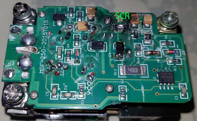
I measured the resistance between pin 5 and 6 as you asked with the diode disconnected. It was not zero but varying from about 2.75Mohm to 4.6Mohm (this is with diode disconnected and the red light on).
I reconnected the diode and tested the shaded pole motor. It tripped consistently 4 out of 5. High probability is an understatement. It's more like consistently.
I reconnected the diode because I was eager to see if the Test button could still work with pin 1 disabled. Lo and behold. When I turned on the unit. There was a red light and loud click as the solenoid kept vibrating (maybe from continuous tripping due to Rset becoming zero). Then the SCR got fried:
Now I remember Meiji telling me that when customers push the reset and test button many times continuous in 2 seconds, the circuit can get fried. So they won't honor warrantee if the customer used it like switches. What kind of SCR did the china clone maker put that can make it burst when the gate is repeatedly triggered??
Refusing to give up without making sure the Test button is not fake. I sacrificed the third and definitely final Meiji GFCI receptacle. Not wanting another fried circuit. I removed pin 6, 1, 2, 3 simultaneously. This happened before and no problem.
I noticed the shaded pole motor no longer tripped. Actually 2 days ago when I first removed pin 6 in the first experiment unit. The motor still tripped 4 out of 5 times. But when I removed pin 1,2,3, the first time I tested it. The shaded pole motor didn't trip for 10 switches. But at 11th time. It tripped so I thought the same old problem. I didn't check it much during that time because focusing on the Test button which seemed to still work. Not long I removed pin 7 and 8 which stopped any trigger then remove the chip by removing the remaining pin 4 and 5.
Now testing the Test button with the third receptacle with missing pin 6, 1, 2,3.. I pressed it a hundred times and only once did it trip. Similarly to shaded pole motor. I switched it about 50 times or more. And one once did it trip.
Analyzing it. I think the chip is simply malfunctioning when the SCR got triggered from 1 in 100 Test button and shaded pole motor switching. Not from inductive kick or Test button leakage but simply the chip doing it 1 out of a hundred. All the pins 4 (ground), 5 (line), 7 (SCR trigger), 8 (trip delay) is still on.
So the inductive kick seemed to affect the input. Since I pulled out the second grounded neutral sense coil 3 days ago and it still tripped. The conclusion seemed to be the inductive kick is causing capacitive coupling in the sense coil input in pin 1, 2, 3. Is this possible? Look at this circuit diagram again:
Note in my first experiment circuit. The second grounded neutral sense coil was pulled out. And pin 6, 1, 2, 3 gone. Since the remaining first sense coil couldn't be the recipient of the inductive kick (could it?), then it's either the capacitor C1 or Rset or Rin or the wires leading to pin 1, 2, 3. Is this possible?
I'm taking time to test all of it because in the Philippines where we were not ruled by UL or NEC. Either people never put any GCFI or a company putting 250 pieces in every outlet. Me too. I'll replace all outlet with GFCI outlet. Mike Holt said this may occur in the US in 2021 so may as well do it now. Hence it is important to know whether the Meiji works. I think it works well. Only problem with it is its manual saying the circuit has UL 2015 auto-monitoring self test which it doesn't.
I can replace the third pcb chip with missing pin 6,1,2,3 from another 2nd pcb with working chip after I upgraded my soldering tool or let my former electronic engineering classmates or professors do it. But I won't yet as I can finally switch the shaded pole motor 50 times or a hundred times with only one trip or so, instead of 4 out of 5 trips in working unit (very consistently).
Besides sense coil pin 1, 2, 3 input wires being recipient of capacitive coupling and inductive kick. Any other theories?


