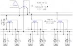
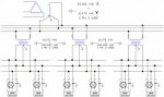
A distribution system where the secondary neutral is connected (bonded) to the substation ground grid, but no multi grounded neutral is brought out of the substation and run along the poles. Hence uni, only one location. Only 3 wires (Phase A, B, C) are up on the pole.
In some 2400/4160Y system out in cali there is a 4th neutral run along the poles but its 100% insulated from earth. So technically that too would count as uni grounded.
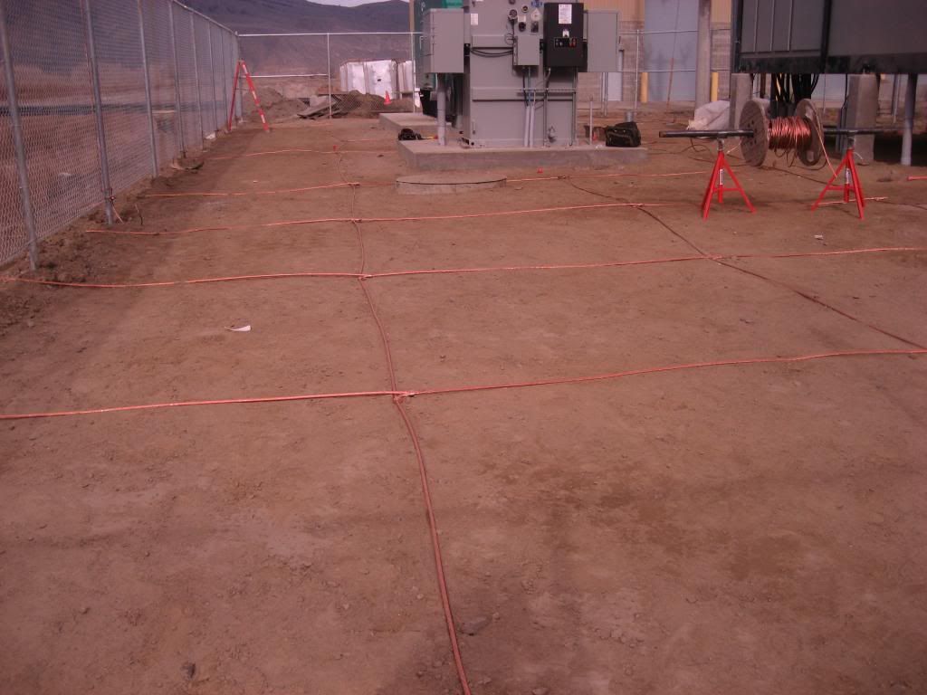
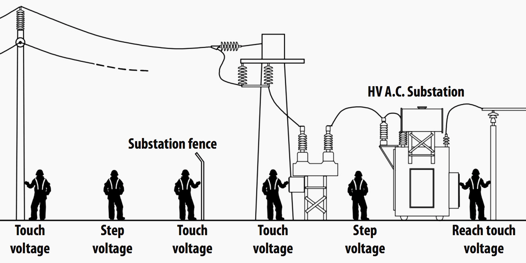
Here is a pic of a substation "ground grid"
Page 9 of what it does, mainly to reduce voltage potential during faults :
https://ccaps.umn.edu/documents/CPE...ts/2017/TutIIISubstationGroundingTutorial.pdf
..............................................................................................
The thing is, and where I must admit my knowledge ends as I can not explain it-
If I have a 7.2/12kv fault to a 25 ohm ground rod 1/4 of a mile from the substation the current will be higher then if I had a fault on the same line 20 miles from the substation on an identical 8 foot 25 ohm ground rod.
However, grounding theory (among others) contradicts this by saying only the resistance of the ground rod (25 ohms) and the substation ground grid (1 ohm) would matter as the earth itself has a resistance of 0 ohms given all the infinite parallel paths which exist.
Theory says that at both 1/4 of a mile and 20 miles the current should always be 276 amps (excluding the impedance of the phase wire of course)
Yet in reality 1/4 of a mile may produce 200amps, while 20 miles down line only 5 amps.
:?:dunce::?
As such a fault at the 20 mile point will cause the phase to ground voltage to rise requiring phase-phase rated insulators and lightning arrestors.
")