MWBC= more heat or Less heat?

Status
Not open for further replies.

rattus

Senior Member
Much ado about not much:

Much ado about not much:

Current through a resistor or resistors is caused by a difference in energy levels at the ends of said resistor. Voltage is a measure of electron energy, therefore it is correct to say the voltage difference causes the electrons to flow--current if you will.

On any one resistor, V = IR. Which came first--current or voltage--does not make a rodent's posterior of difference anyway.

Ohm's law holds at zero resistance, but you have to sneak up on it by taking a limit as R approaches zero. Exception is zero ohms across an ideal voltage source because division by zero is undefined.

Not that we will ever encounter zero resistance!

And, BTW, the MWBC can reduce the power loss in the wiring by a factor of two.
 

david luchini

Moderator
Staff member
Location
Connecticut
Occupation
Engineer
Man, we seem to be arguing all over the place.

Originally, you stated that current can flow in a neutral even though no potential existed across that neutral. Now you are saying that current cannot flow under zero potential. What gives?

Of course, your conjecture above cannot be proven. When we get to the point of zero resistance, it may very well be that quantum effects cause the electrons to go rocketing all over the place. Saying that a potential is required to move an electron through a zero impedance is equivalent to saying that there is some sort of impedance in that zero impedance.

You are saying that a zero impedance contains some quality which prevents electrons from moving unless a voltage is applied? Again, if this is what you are thinking, then a zero resistance is not really a zero resistance.... zero resistance actually has resistance? Maybe the electrons have inertia which must be overcome? But does Ohm's law say anything about that?

Zero resistance is getting into the realm of quantum mechanics where electrons are not little balls being kicked around. They are waves which behave by different laws than Ohm's.

Crossman gary, you are still not understanding what I have said. An argument was put forth early in this thread that said the reason no current flowed down the neutral of a balanced MWBC, was because there was not potential difference across the neutral wire from load to source, that it was the potential difference (or voltage drop) along the conductor that caused the current to flow along the conductor.

I demonstrated that this idea, was in fact wrong. Current can flow along an ideal conductor (with no voltage drop.)

What I have said, is that a potential source and a closed circuit are required to flow in the circuit. If the voltage of the potential source in the circuit is reduced to zero, that is there is no potential source on the circuit, then current will not flow in the circuit. What is confusing about that?
 

david luchini

Moderator
Staff member
Location
Connecticut
Occupation
Engineer
And the intent of the above was directed to David who in some posts has said that current can travel through a conductor even though no potential difference exists across it, and in other posts he has said that current cannot flow in a conductor unless a potential exists across it.

Again, NO. What I said is that current can travel through a conductor that has no potential difference (voltage drop) along it.

In the other post I said that current cannot flow in a CIRCUIT without a potential source applied to it.

These two concepts are both correct. And they are not contradictory.
 

LarryFine

Master Electrician Electric Contractor Richmond VA
Location
Henrico County, VA
Occupation
Electrical Contractor
And the fact that every thermocouple in a furnace uses this to generate enough power to open a gas valve without any external power supplied;)
Of course, thermocouples work by heating the junction of two dissimilar metals.
 

david luchini

Moderator
Staff member
Location
Connecticut
Occupation
Engineer
At ease there little buckaroo, this forum is not populated with hacks, hicks, and idiots. Instead of addressing issues that quite knowledgeable people bring up, you have a tendency of sidestepping them with belittling comments. You might want to be a little more careful with what you say and how you say it.
Rick, exactly what issue have I side stepped? I have addressed every issue that has been brought up in this discussion.

Oh man! I am at a compete loss here. I just looked up your profile and you are listed as not only an E.E, but a P.E. too. We should not be having this caliber of discussion with your credentials. When I wrote my previous message, I mistakenly assumed that your education was not that of an EE. This is not a topic that I should need to explain to a PE, EE. You have the appropriate education, so there is no reason for me to explain how to convert from an ideal circuit to a real circuit. (I mean no offense, but you really caught me off guard with this.)
You mean like that belittling comment?

For example, here you tell the poster that he doesn't understand Ohm's Law, and then you go on to make a complete misstatement of Ohm's Law. Please explain how Ohm's Law does not predict an increase in current when the voltage is increased for a given circuit
I gave an explanation to the poster how he was misunderstand Ohm's Law. Did you not read the explanation? And I did not make a complete misstatement of Ohm's Law. Ohm's law does NOT say that an increase in voltage will cause an increase in current in a circuit. Ohm's Law says that the current through a conductor between two points is directly proportional to voltage across the two points, and inversely proportional to the resistance between them. Expressed mathematically, this is I=V/R. BOTH the voltage and resistance affect the current. If, in the ideal circuit that crossman gary described, the resistance of the circuit is 0, then the current flow is infinite (this is a short circuit.) Changing the voltage, will have no affect on the current, because BOTH the voltage and resistance affect the current. When the resistance in the circuit is zero, Ohm's law tells us that the voltage can be any value (other than zero) and the current will not change. This is an accurate statement of Ohm's law. (Technically, in this ideal circuit's short circuit (where circuit R=0,) "changing the voltage" is a non-issue because there is not voltage drop in the short circuit.)

...were to point out that you are suggesting that there is some sort of difference between a "potential source" and any other type of "potential difference." The electrons don't care where or why a difference in potential exists.
Again, no. An active electrical network must contain at least one active element, such as a voltage source or current source. (I think we can ignore current sources for our discussions.) A circuit (other than a short circuit) will also contain passive elements such as resistors, inductors, capacitors. The active element in the circuit is capable of delivering power in the circuit, while the passive elements receive power (or receive, store, and return the power later, ie, capacitor.) It is the active voltage source that causes the current to flow in the circuit. Cleary, THERE IS a difference between the voltage source in the circuit and the voltage drops in the circuit. The voltage source provides power to the circuit, while the voltage drop is an absorbtion of power from the circuit. They are not the same. While the electrons may not care why the difference in potential exists, it is only the voltage source that is causing them to move. We have demonstrated that current will flow along an ideal conductor with no voltage drop, so clearly the voltage drop in not causing the current to flow.

You don't see the contradictions in these statements? :confused: If the voltage drop across a conductor doesn't cause electrons to move, nor do they move because their neighbors push them, then how do the electrons know that a voltage differential exists in order to move?
No, I do not see a contradiction in my statements, maybe poor wording. Reread the part before that. A potential "source" (I mispoke using the word "difference" there - but I think I have been clear in making this point in several posts) and a closed circuit path are required to cause current to flow. The voltage drops along the circuit are not Active, but Passive in the circuit. They do not cause current flow, they are a result of current flow.

I beileve it is you that has lost sight of the basic concepts behind electrical systems, specifically, electron movemement. An electron will not move unless there is a force acting on it (ignoring drift and inertia, as those are separate topics).
Yes, an electron will not move unless there is a force acting on it. However, this force IS the voltage source (the active element in the circuit,) not the voltage drops in the circuit. And no, I haven't lost sight of the basic concepts behind electrical systems. I am quite clear on the concepts, and believe I just explained them in a clear and concise manner.

Do they pass the word along from electron-to-electron that somewhere way up the circuit someone has connected a power supply? (oops, just in case you didn't realize it, like the Radio Shack comments, that was a contemptuous joke, not intended to be percieved as scientific intercourse.)
And by the way, I apologize for my earlier tone. I had just gotten out of a less than enjoyable meeting.
 
Last edited:

LarryFine

Master Electrician Electric Contractor Richmond VA
Location
Henrico County, VA
Occupation
Electrical Contractor
Just to reiterate: If a voltage difference would exist with the conductor absent, then the presence of the conductor permits a current.

Even if the conductor has zero voltage drop, the above statement is still true. Not every segment of a circuit has to have voltage drop.
 

ELA

Senior Member
Occupation
Electrical Test Engineer
And the fact that every thermocouple in a furnace uses this to generate enough power to open a gas valve without any external power supplied;)

That sounds like a pile to me!
 

crossman gary

Senior Member
He assumed ideal conductors, which is perfectly acceptable, but then started looking at the behavior of the individual conductors while still using this same assumption that they were ideal.

You use this assumption when examining the load is your primary goal, but when you switch over to examining how/why current flows in the actual conductors, you can no longer treat them as being ideal conductors.

Bingo. This concisely sums up the issue. Thanks Rick.
 

crossman gary

Senior Member
And to follow up on the Ohm's Law issue. Everyone seems to think that it is some immutable, always correct under any circumstance, natural law. Well, other laws certainly fail under extremes, for example, Newton's laws of motion. Why not ohm's law also? For the most part, all classical natural laws fail to properly predict what is happening when dealing with extreme cases. This is the realm of relativity and quantum mechanics.

For example, ohm's law places no restrictions on using infinitely divisible numbers for voltages and currents. We could put numbers into ohm's law which would result in say, 1/4 of an electron flowing. However, when we investigate the extremely small, you will find that theory says these quantities are governed by quantum mechanics. I don't claim to have any knowledge of quantum mechanics, but I would be extremely surprised if Ohm's Law didn't have shortcomings when dealing with individual electrons.

Someone mentioned the inertia of individual electrons. I feel certain that newtons inertia does not apply to an indivdual electron which is governed by the probabilities of quantum mechanics. My elementary knowledge leads me to believe that the motion of electrons in a superconductor are governed more by quantum mechanics than by ohm's law and newton's laws of motion.

Remember, those electrons are not little billiard balls bouncing around. There is a wave-particle duality and collapsing probability waves that predict what is happening.

And I feel certain that ohm's law fails when applied to perfect ideal infinite sources and zero resistance conductors.
 

crossman gary

Senior Member
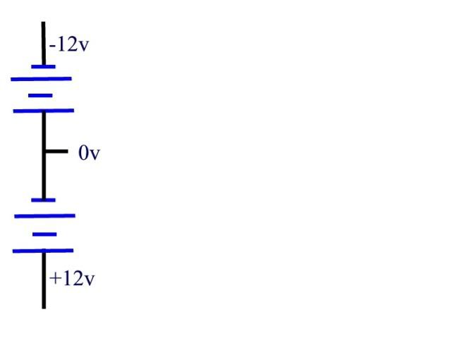
Starting with two 12 volt batteries which are ideal and infinite with no internal resistance as follows:

applesource.jpg


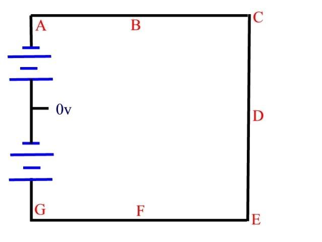
Now connect a "load" consisting of a conductor with zero resistance across the batteries as shown below:

appleshort.jpg


With respect to the centerpoint between the batteries labeled as 0v, please assign voltages/polarities to the other points A through G.

A couple of people said/implied that all of the voltage measurements, A through G, are zero. But that is a contradiction. We are dealing with perfect and infinite sources and that voltage across them cannot simply just dissappear. Was it dropped in the source? Can't be. There is zero resistance in those sources. The measurment to A has to be -12 and the measurement to G has to be +12 based on the ideal infinite sources.

Those who believe that Ohm's law is akin to a decree from god have some explaining to do. Either that, or I really need someone to teach me what is going on here.
 

LarryFine

Master Electrician Electric Contractor Richmond VA
Location
Henrico County, VA
Occupation
Electrical Contractor
I'm appreciative that we've kept this civil enough that The Mod Squad hasn't seen fit to jump in.

Bravo all! :smile:
 

crossman gary

Senior Member
Ohm's law holds at zero resistance, but you have to sneak up on it by taking a limit as R approaches zero. Exception is zero ohms across an ideal voltage source because division by zero is undefined.

Thank you rattus. I understand what you are saying. As long as a source has internal resistance, then we can deal with a zero resistance circuit. But as you say, Ohm's law will not work for an infinite source and a zero resistance. So my conjecture seems correct.

And, of course, when dealing with limits, as you know, and can be acknowledged in any calculus text:

"arbitrarily close to zero" and "equals zero" are two different things. The limit you mention above, while giving correct answers as the resistance approaches zero, may fail entirely if we actually let the resistance equal zero.

With either integration or derivation, if dx ever actually equals zero, the entire thing blows up in our face.
 

crossman gary

Senior Member
I'm appreciative that we've kept this civil enough that The Mod Squad hasn't seen fit to jump in.

Bravo all! :smile:

Larry, every time I have logged on today, I have pretty much been expecting to find this thread nailed closed.:wink:

Maybe we will get a reprive. Although I am thinking that it has pretty much run its course unless someone can explain my drawings or your picture.
 

hurk27

Senior Member
A couple of people said/implied that all of the voltage measurements, A through G, are zero. But that is a contradiction. We are dealing with perfect and infinite sources and that voltage across them cannot simply just dissappear. Was it dropped in the source? Can't be. There is zero resistance in those sources. The measurment to A has to be -12 and the measurement to G has to be +12 based on the ideal infinite sources.

Those who believe that Ohm's law is akin to a decree from god have some explaining to do. Either that, or I really need someone to teach me what is going on here.

Ok I'll bite

The batteries heat up till they explode:rolleyes:

The problem with the terms Infinite when used in both the source and load leaves no room for anything to give, because of the infinite resistance will always short out the infinite source. one or the other have to give or the current will just keep going up. we have the same problem with the term "forever"
and we all know these terms can not be a part of a real world. at least in our knowledge.
 

david luchini

Moderator
Staff member
Location
Connecticut
Occupation
Engineer
Originally Posted by Rick Christopherson
He assumed ideal conductors, which is perfectly acceptable, but then started looking at the behavior of the individual conductors while still using this same assumption that they were ideal.

You use this assumption when examining the load is your primary goal, but when you switch over to examining how/why current flows in the actual conductors, you can no longer treat them as being ideal conductors.


Bingo. This concisely sums up the issue. Thanks Rick.

Thank you, but, No, I did not "assume" ideal conductors, that then start looking at the behavior of individual conductors while still using this same "assumption" that they were ideal.

I have looked at "ideal" conductors and how they would perform in "ideal" circuits, and I have looked at "real" conductors and how they would perform in "real" circuits. But no where have I projected an "ideal" conductor into an analysis of a "real" circuit.

I think this forum is an important learning tool, and some people in this discussion seem to have the incorrect idea that the "voltage drop" along a conductor is the "force" that causes the current to flow through that conductor. I have attempted to show through various discussions, including providing examples, why this belief is untrue. Yet instead of providing counter arguments to my points, several poster respond with:
I am "assuming" this, or I have "contradicted" myself with that, or I am missing a "minus sign" which will give me the wrong answer in an equation, even though in the answer my equation provided was the correct answer.

If you have a disagreement with one of my posts, then provide a counter argument with examples to back up your argument. By doing this, this forum will be an educational opportunity for all of us.
 

david luchini

Moderator
Staff member
Location
Connecticut
Occupation
Engineer
A couple of people said/implied that all of the voltage measurements, A through G, are zero. But that is a contradiction. We are dealing with perfect and infinite sources and that voltage across them cannot simply just dissappear. Was it dropped in the source? Can't be. There is zero resistance in those sources. The measurment to A has to be -12 and the measurement to G has to be +12 based on the ideal infinite sources.

Those who believe that Ohm's law is akin to a decree from god have some explaining to do. Either that, or I really need someone to teach me what is going on here.

crossman gary, I don't believe that Ohm's law is akin to a decree from god. As far as I know Ohm was just a man, as well as, Kirchhoff, Volta and Amp?re. Though, I suspect all of them were men of exceptional intelligence.

Let me try to explain why the voltage measured across all points in your illustration will be zero (credit to Larry, as he was the first to suggest the voltage drops will be zero.) You had specified two 12 volt batteries with zero internal impedance, and an ideal conductor with zero impedance. Lets, for argument, put a 24 ohm resistor between C and E in your circuit before we consider your short circuit. I think you will see from Ohm's Law that 1 Amp will flow through the resistor, and that the voltage drop will be 24 volts in the circuit from C to E.

Now lets apply the ideal short circuit that you have drawn across C-E. The resistance from C-E will be zero ohms for the ideal conductor. So, look at Ohm's law applied across C-E. If V=I*R, and R=0, we will have V=I*0. Provide any value of current that you want into the equation V=I*0, and the voltage drop will ALWAYS be zero. So for the ideal short circuit that you have drawn, the voltage drops across any two points that you have drawn will also be zero, because the resistance between those two points. Now, you wonder why is the voltage drop across your two batteries also zero. Kirchhoff's Voltage law tells us that the sum of the voltage drops in a closed loop circuit will sum up to zero. In your illustration, Vab+Vbc+Vcd+Vde+Vef+Vfg+Vgo+Voa=0. If the voltage drops across all of the points that you drew on the load side of the circuit, then the voltage drops across your two sources must also be zero.

In a real world power system, when a short circuit occurs, there is also a corresponding voltage drop on the system. For example, consider a 75kVA, 480-208/120V transformer with a 2.5% impedance. On the low side, the rated transformer secondary current is 208 Amps. The maximum current that could flow into a short circuit on the secondary side is calculated as 208Amps*100%/2.5%=8320 Amps. Of course, the amount of current flowing during a short circuit condition will depend on where the short occurs in the circuit, because the farther we are from the transformer, the more impedance there will be in the circuit because of the impedance of the circuit conductors. Lets say the short circuit for this transformer occurs very near the transformer so that the short circuit current will be the full 8320 Amps. The transformer, of course, is a limited power device, it is rated to deliver 75kVA. (The "ideal" battery that you specified with zero internal impedance can theoretically deliver infinite power.) The voltage we would expect to see on this circuit during a short circuit would drop to to 5.2Volts.

Since you have an ideal circuit, the voltage on your circuit will ideally drop to 0 Volts. I hope this explanation is clear and understandable.
 
Last edited:
Status
Not open for further replies.
Top