Gar,
Thanks for your comment. I agree with you this is getting more complex than I ever intended. I didn't see much in these waveforms but posted them because others here asked to see them and since I'm neither an EE or electrician I figured it was worth doing that much.
I do try to stop myself every once in a while when investigation of problems like this keeps growing in complexity. I repeat the questions, what exactly is the problem? What's the root cause? How can I avoid going down so many rabbit holes?
The problem here, at least the manifestation of the problem that bothers the client, is a noisy conduit. I've stated already we're confident now the frequency is 120 Hz and does not vary other than in amplitude, and it's tough to nail the amplitude down because it's constantly changing as solar conditions change. It appears to be loudest not just when PV production is at it's peak but dynamically as PV production is ramping as clouds clear away. It actually appears to modulate down a bit in amplitude once clear skies prevail. But it's always loudest when PV production is over 80% and unfortunately I've not been able to observe those conditions in the two weeks I've been on the job so my ability to gather observations has been limited and I'm relying on the client's commentary. I would like, as it appears you suggest, to determine how the amplitude varies along the length of the conduit but I am not currently tooled up for that and am considering how to become tooled up based on suggestions made to me in this thread so far.
Which is a long way of saying that the *root* cause so far has been a moving target.
Either way, it is very clear that the proximate cause of the noise is obviously strongly vibrating conductors.
We have established that the vibrating conductors clearly have strong magnetic fields being generated between them. This was accomplished by trying out several different phone app Gauss meters, at first one that simply totaled the fields, eventually finding one that measured them in 3 axes.
(These are tools I did not know were so readily available and would never have thought of without being prompted by observations from interested parties on this forum. As I stumble through this part of my investigation I've reported here my less than scientific findings because I'm frankly fascinated by the it all and, evidently, others are as well, as referenced by comments such as "waiting with baited breath" and even one offline conversation where I was told I have a moral obligation for follow through and report out my findings. Again, not an electrician, not an EE, and I’m learning about this stuff by leaps and bounds over the last week. Again, plenty of electricians, the EE of record, and the utility have spent 2 years looking at this problem and in the first 2 minutes I found found hot spots they never knew existed, and have made more progress over the last 2 weeks than all of those people combined. With all due credit to this forum for all the help I’ve received from y’all.)
Those fields - to me anyway - appear to be anomalous. Perhaps I've missed it but I don't believe anybody here as said to me that they are normal and acceptable. They are certainly not desirable in this case. Even if the fields are normal, my long experience in thermography leads me to believe that even if we figured out a way to dampen the sound in the conduit, if we don't make the wires stop vibrating we will very likely still end up with compromised connections at either end of these long cable runs, with unreasonable maintenance costs to prevent component failures if we don't figure out WHY those vibration inducing fields exist and mitigate that condition as well.
It's because I don't know the answer to that I came here to ask people with much more knowledge and experience regarding such things. Along the way a whole lot of questions came back at me and I've been doing my best to respond to those questions, and yes along the way this thread has grown perhaps unnecessarily complex with potentially irrelevant details. I do apologize for that and I've repeatedly expressed my thanks for your continued indulgence of my relative inexperience - I did ask in my opening post that you please bear with me as I'm neither an electrician nor an EE, just a thermographer who normally finds hot spots, points, and says "you might want to fix that." (Although I actually am an environmental engineer normally focused on energy efficiency and industrial reliability. The EE stuff is just a little outside my academic background).
So the one thing I do know is that there are components in this circuit operating out of spec thermally. I have prescribed measures to remediate those conditions and that work is scheduled to be completed this week.
But I've seen similar situations hundreds of times, usually in timber mills where they don't care about the noise. They'll tighten or renew connections, or even replace components in some cases, and the problem comes right back because there's something fundamental in the circuit causing vibration that they still haven't addressed.
This has bothered me for years and I finally have a client who really wants to get to the bottom of it and understand what's going on. Both the client and the installing electrician are very invested in solar development and they want to understand what’s happening as much as I do. Consequently I'm pretty motivated to analyze the heck out of it, accounting for every variable I can identify and scratching them off the list one by one until we can definitely state: THIS is the root cause of this problem. THIS is the solution that will fix it permanently. And THIS is what we can incorporate into our designs and/or maintenance procedures to ensure we don’t encounter it again elsewhere.
So far, there is no one variable that is obviously the answer, and there are a lot of them waiting to be scratched off the list.
Is there a subpanel somewhere in the building I don't know about where somebody bonded neutral to ground? I'm going to look in to that.
Did the medical office tenant who moved in after the array went live install a big THD-inducing UPS in the server room they guard so carefully? We've asked and are awaiting answers.
Does the utility transformer outside the building have a compromised ground or neutral bond? We've asked them to rule that out.
Did the whole thing start because the inverter combiner box breaker panel came with breakers pre-installed and the bolts bonding those breakers to the bus were never torqued in the field by the installing electrician? That question only arose late Friday afternoon because it would never have occurred to me had he not brought it up, prompted by so many prodding questions asked by me. You can bet your sweet bippy we'll be taking a much closer look at those components over the next couple days.
One way or the other, we'll get to the bottom of this. I am hopeful that very soon this ever widening scope is going to become dramatically more narrow until we are laser focused on just one or two things.
Along the way I will continue to express my gratitude and can assure you I'll report out in the briefest and most concise terms possible what I've learned upon this investigation's conclusion.
(TLDR version: Gar, you're right. Point taken. But also, a bunch of other stuff.)
Thanks again,
Redwood Infrared
180616-2433 EDT
Redwood Infrared:
I think your troubleshooting procedure is unnecessarily complex.
My guess is that many things you are spending time or thought on are not likely to have anything to do with the problem.
One time I had some quality control people that came to me and said they were getting too much pinion position variation from the pinion shim station. They wanted to do some statistical studies to try to isolate the cause. Was it, parts, the pinion shim machine, or something else? This is the long hard way to find the problem if there are other approaches.
I went over to the machine and ran some simple tests. Within less than 15 minutes, including walking time, I told them there was a bad thrust bearing in the pinion shim station. Their experiments would have taken days, product yield would have been bad all that time, and their approach may not have foumd the problem.
You have an acoustic noise problem. You need to know what that signal looks like, and have measured values from it. You need to know how this signal varies over a spatial area. You need to know what items are vibrating and possibly amplifying the sound level. With this information you can better focus your attention on the likely cause.
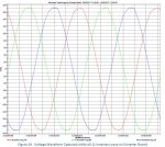
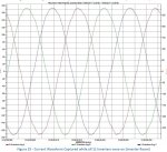
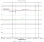
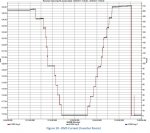
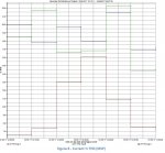
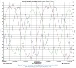
Your waveforms are of little value at this time. Your neutral current is dominantly a single phase 60 Hz sine wave of low magnitude. Probably unimportant.
You might do some bench tests with single and three phase wires loose in a conduit and see if you can create acoustic noise.
Your last post implies quite different plant loads on each phase. Each individual phase looks repetitive, but each is different from the other two phases.
.