"Mystery Current" burns up cable splitters

Status
Not open for further replies.
Unfortunately comments didn't help me any. Wish I had a gauss meter but I don't.

Still have a hard time believing that high of a current in the test loop due to power lines measured at a distance.

I could see this working if you were directly under (a single conductor) power line carrying 100 amps or more such that you did not have any magnetic field cancelation from adjacent wires.
Even then the coupling into a ring would not be very efficient at any appreciable distance.
 
Here is what I am thinking about:

In a generator, we have a north pole on one side of the conductor loop, and a south side on the other side of the loop. Each side of the loop in the generator is cutting the flux lines in opposite directions, which causes the voltage on each side of the loop to be additive. That is not the case with the 5 foot copper circle of wire.

Basically, the magnetic field of the power lines is cutting across one side of the loop in a certain direction, and then 5 feet away, it is cutting the other side of the loop in the same direction. The voltage in one side of the loop opposes the voltage in the other side of the loop. So, the only flux that could cause a current flow in the 5 foot loop would be the DIFFERENCE in the magnetic field over the 5 feet diameter of the loop.

Now, considering that we are, oh, 200 feet from the 230kv powelines to start with, the difference in the flux across the 5 foot loop would be negligible.

I'm definitely not the expert here, just relying on my elementary understanding of electrical phenomenon. Any comments?
Picture1-1.jpg
 
ELA said:
Unfortunately comments didn't help me any. Wish I had a gauss meter but I don't.

Still have a hard time believing that high of a current in the test loop due to power lines measured at a distance.

I could see this working if you were directly under (a single conductor) power line carrying 100 amps or more such that you did not have any magnetic field cancelation from adjacent wires.
Even then the coupling into a ring would not be very efficient at any appreciable distance.

Try looking at the enclosed link (page 38).It plots typical magnetic fields versus distance.Of course,higher load currents will create higher magnetic fields.We have measured over 500 power line-magnetic fields.

Good luck with your theories.

http://www.niehs.nih.gov/health/topics/agents/emf/docs/emf2002.pdf
 
Here is a better diagram showing my point:

The point is, that opposite sides of the loop will try to make the current flow, for example in my diagram (arbitrarily), from left to right.

If we took two seperate conductors and spaced them 5 feet apart, certainly the voltage polarities would be in the same direction. If we simply connect the two ends together, the voltages in each side of the loop would oppose each other.

Now, the conductor which is 200 feet away would have a somewhat larger flux cutting it than the one which is 205 feet away. But would it be enough to make 1 or 2 amps flow?

I am still doubting this. Am I missing something?

(The diagram should probably say "volts" instead of amps.
Picture1g.jpg
 
ghostbuster said:
The magnetic field measured and witnessed by the utilities and the electrical inspection dept. was between 100-150 milligauss.

The pamplet that you mentioned entitled "EMF Questions & Answers" stated that a typical microwave oven in your kitchen produces around 200 milligauss. So my microwave oven would actually be stronger magnetically than that 230 kv powerline at approx 200 feet.

I'll have to try a 5 foot loop at my microwave oven.
 
ghostbuster said:
Try looking at the enclosed link (page 38).It plots typical magnetic fields versus distance.Of course,higher load currents will create higher magnetic fields.We have measured over 500 power line-magnetic fields.

Good luck with your theories.

http://www.niehs.nih.gov/health/topics/agents/emf/docs/emf2002.pdf

Thanks Ghostbuster. Page 37 was interesting and I will read more when I have time. Page 37 demonstrates to me that it is unlikely you would measure 2 amps in a ring at a far distance from the power lines.

I am no magnetic field expert. When I do not understand something at a theoretical level I sometimes perform practical experiments to help better my understanding.
I have no doubt that magnetic fields exist around power lines. My point is that it would take a very large field or a very close distance to induce 2 amps in the test ring in question.

With your knowledge and experience in magnetic field testing can you explain what type of field strength it would take to induce 2 amps into the 5ft test ring at 100,200 or 300ft?
 
Larry, it is my understanding that microwave frequencies carry much more energy than a 60 hz field. I'm sure there would be some destructive issues arrising out of placing the copper wire in the microwave.;)

Do you have any thoughts on my diagrams though?
 
crossman said:
Here is a better diagram showing my point:

The point is, that opposite sides of the loop will try to make the current flow, for example in my diagram (arbitrarily), from left to right.

If we took two seperate conductors and spaced them 5 feet apart, certainly the voltage polarities would be in the same direction. If we simply connect the two ends together, the voltages in each side of the loop would oppose each other.

Now, the conductor which is 200 feet away would have a somewhat larger flux cutting it than the one which is 205 feet away. But would it be enough to make 1 or 2 amps flow?

I am still doubting this. Am I missing something?

(The diagram should probably say "volts" instead of amps.
Picture1g.jpg

If I remember right, all the flux flowing through the internal area of the ring of wire adds together to produce the EMF and current in the ring. IN math terms I think it is the something the EMF equals integral of flux over the area of the ring.

However, the flux produced by the three different phases of the power lines would tend to cancel each other out, even directly under the lines.

Steve
 
ELA said:
Thanks Ghostbuster. Page 37 was interesting and I will read more when I have time. Page 37 demonstrates to me that it is unlikely you would measure 2 amps in a ring at a far distance from the power lines.

I am no magnetic field expert. When I do not understand something at a theoretical level I sometimes perform practical experiments to help better my understanding.
I have no doubt that magnetic fields exist around power lines. My point is that it would take a very large field or a very close distance to induce 2 amps in the test ring in question.

With your knowledge and experience in magnetic field testing can you explain what type of field strength it would take to induce 2 amps into the 5ft test ring at 100,200 or 300ft?

ELA

With the 5' test ring positioned perpendicular to the resultant magnetic field(to maximize the field pick-up),and a low impedance test coil,magnetic field values ranging between 100-200 milligauss should produce 1-2 amps of 60 hz. induced current flow (refer to Biot-Savart Laws for the integral equations and Maxwell eqns. etc.).
 
ghostbuster said:
ELA

With the 5' test ring positioned perpendicular to the resultant magnetic field(to maximize the field pick-up),and a low impedance test coil,magnetic field values ranging between 100-200 milligauss should produce 1-2 amps of 60 hz. induced current flow (refer to Biot-Savart Laws for the integral equations and Maxwell eqns. etc.).

Thanks for your input. Not being an expert in magnetic field mathamatics I will pass on the equations for my own use. However I did find the following link. I cannot say whether or not it is accurate but plugging in 10 amps for wire #1 and a 0.025 meter (1") separation between wires it presents 800 mg. And my wires were even closer than 1 ".
The values I used are representative of the test I did.

http://hyperphysics.phy-astr.gsu.edu/hbase/magnetic/wirfor.html#c1

In the test I tied wire #1 directly to wire #2 matching circumferences for maximum coupling. This is way different that holding a ring a couple hundred feet from power wires.

If the link I provided is not being used properly perhaps you could present the "Biot-Savart Laws for the integral equations and Maxwell eqns. etc" solution.
 
I am totally missing the theory which could cause 1 to 2 amps of flow in the ring.

Let me further explain my thoughts, hopefully someone will set me straight.

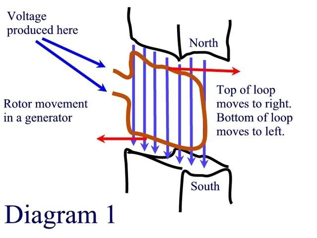
Diagram 1: A generator. Note that the top of the loop goes one direction through the flux, the bottom of the loop goes in the other direction through the flux, and, because of the opposite polarites created, the voltage in the top of the loop and the voltage in the bottom of the loop will add together creating an overall voltage.

Diagram1.jpg


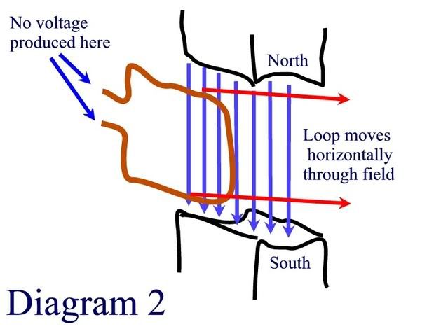
Diagram 2: Now, instead of rotating the loop, we simply move it horizontally through the field. The voltage polarities of the top and bottom are the same, and they cancel out, leaving no overall voltage on the loop. It does not matter whether the loop moves or the flux moves. The flux is cutting both wires in the same direction.

We can use the left hand rule for determining the polarity, but arbitrarily, say the top of the loop has negative to left, positive to right. The bottom of the loop will have the exact same polarity, negative to left, positive to right. And we are connecting the positive to the positive, which makes the two voltages cancel.

Diagram2.jpg

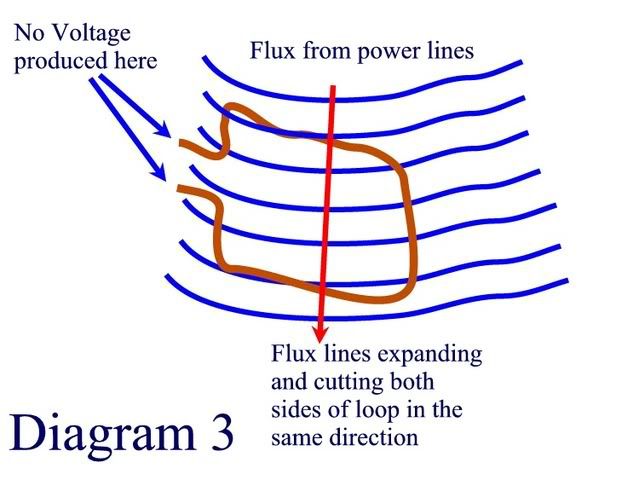
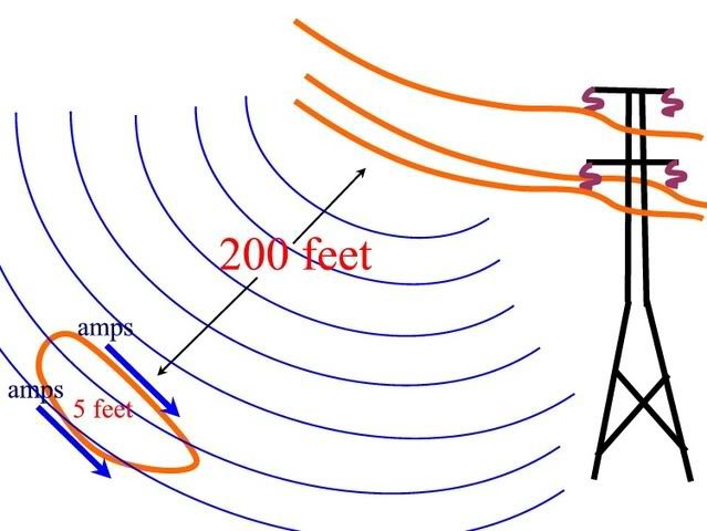
Diagram 3: Shows the power line flux cutting the top of the loop and the bottom of the loop, both in the same direction. The exact same scenario is set up as in diagram 2. No voltage produced. Well, the only voltage actually produced is that the top of the loop is closer to the magnetic field and will have a slightly stronger flux density than the bottom of the loop. Only this difference of flux density will produce a voltage in the loop.

Say the top of the loop is 100 milligauss. The bottom of the loop is 95 milligauss. Only 5 milligauss will produce voltage.

Diagram3.jpg


Now, if we were to rotate the loop, then maybe we can create some significant voltage.

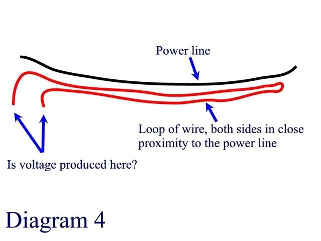
One more thought - Diagram 4

If both sides of the loop are in close proximity to the power line, no voltage is produced because the voltage in each loop is opposite of the other. Hopefully this will get the point across about my claim that the voltages on each side of the loop would cancel.

Or am I wrong?

Diagram4.jpg
 
ELA said:
The values I used are representative of the test I did.

http://hyperphysics.phy-astr.gsu.edu/hbase/magnetic/wirfor.html#c1

In the test I tied wire #1 directly to wire #2 matching circumferences for maximum coupling. This is way different that holding a ring a couple hundred feet from power wires.

I would have to say that you need to do the calculations for the top side of the loop and for the bottom side of the loop. Both sides of the loop create a voltage, and these voltages will subtract from each other, not add.

For example:

For the top of the loop, let 500 amps flow in wire 1 and have the distance be 200 feet. Calculate voltage

For the bottom of the loop, let 500 amps flow in wire 1, and have the distance be 205 feet. Calculate voltage

Now subtract these two voltages to get overall voltage of loop.

And, this is ignoring the fact that much of the magnetic field will be cancelled by the other phase conductors on the tower before they ever have influence on the loop.
 
crossman said:
Do you have any thoughts on my diagrams though?
Yes, and even without your additional drawings above, I agree with you. Even a wire loop between two HV conductors would have to rotate to develop any appreciable current.
 
crossman said:
And, this is ignoring the fact that much of the magnetic field will be cancelled by the other phase conductors on the tower before they ever have influence on the loop.
It's aslo ignoring the fact that a closed loop (or one incorporating an ammeter) would be of such a low impedance that the open-circuit induced voltage would be eliminated.
 
Crossman:

Its slowly starting to come back to me. It is the rate of change of the flux through the loop that creates the current flow. Picture the current flowing down one wire of the transmission line at one instant of time. Your thumb is the current flow, and your fingers wrap around the wire in the direction of the magnetic flux around the wire.

Now as you get farther out from the transmission line, your fingers still point in the direction of the flux. Picture your fingers going through the center of the loop of wire. This creates a current in the direction of your thumb in the loop of wire. If you twist your wrist to make your thumb follow the loop of wire, you will see that all the flux creates current flow in the same direction.

The thing to remember is it is the area of the center of the loop that determines what current is induced. Not the flux passing through the length of wire.

Steve
 
Last edited:
I have to disagree with you, Steve. All of my studies and reading make me believe that voltage is produced only when the flux lines cut through the conductors. This cutting action through the wire is what causes the electrons to "want" to move. The external magnetic field reacts with the electrons magnetic field and put a force on them.

I don't think it has anything to do with the center of the area of the loop.

I will stand by my diagrams above until further evidence presents itself.

Thaks for the input, and look forward to further dialogue.:smile:
 
ELA said:
Thanks for your input. Not being an expert in magnetic field mathamatics I will pass on the equations for my own use. However I did find the following link. I cannot say whether or not it is accurate but plugging in 10 amps for wire #1 and a 0.025 meter (1") separation between wires it presents 800 mg. And my wires were even closer than 1 ".
The values I used are representative of the test I did.

http://hyperphysics.phy-astr.gsu.edu/hbase/magnetic/wirfor.html#c1

In the test I tied wire #1 directly to wire #2 matching circumferences for maximum coupling. This is way different that holding a ring a couple hundred feet from power wires.

If the link I provided is not being used properly perhaps you could present the "Biot-Savart Laws for the integral equations and Maxwell eqns. etc" solution.

ELA

Try this link(biot-savart) from the same source you are attempting to use.

I plugged in 2 amps and .5 metres and got 25 milligauss.(it gets you in the ballpark)

Note:cable impedance plays a big part at these magnetic field levels in obtaining higher induced currents

http://hyperphysics.phy-astr.gsu.edu/hbase/magnetic/curloo.html#c1


Good luck
 
crossman said:
I would have to say that you need to do the calculations for the top side of the loop and for the bottom side of the loop. Both sides of the loop create a voltage, and these voltages will subtract from each other, not add.

For example:

For the top of the loop, let 500 amps flow in wire 1 and have the distance be 200 feet. Calculate voltage

For the bottom of the loop, let 500 amps flow in wire 1, and have the distance be 205 feet. Calculate voltage

Now subtract these two voltages to get overall voltage of loop.

And, this is ignoring the fact that much of the magnetic field will be cancelled by the other phase conductors on the tower before they ever have influence on the loop.

Crossman,
I agree with what you are saying about inducing equal and opposite currents on opposite sides of the coil from a remote field. That is not what I did in my test.

Just for the purpose of testing the coil and coupling effectiveness I ran a current carrying wire around the entire perimeter of the test coil (current flow all in the same direction).
This was just for the purpose of getting a rough idea of coupling efficiency in a most ideal situation.

In this case there was no field cancellation and of course not realistic to the power line situation.

I did not see the test ring as being very effective in a true power line test.
 
ghostbuster said:
Try this link(biot-savart) from the same source you are attempting to use.

I plugged in 2 amps and .5 metres and got 25 milligauss.(it gets you in the ballpark)

http://hyperphysics.phy-astr.gsu.edu/hbase/magnetic/curloo.html#c1

The magnetic field produced by the power line is going to be of a completely different geometric form than that provided by the instance above. In the link above, you are putting 2 amps in the loop and creating a magnetic field around the loop. In the power line situation, we have magnetic flux radiating from the overhead wires affecting the loop. Looks like an entirely different situation to me.
 
Status
Not open for further replies.
Top