winnie said:
I like the way you are thinking, but I belive that you have made a few errors.
Thanks for the complement, and there is no doubt I have been wrong before, and will be again!:grin:
winnie said:
In post #37, you make a differentiate between flux lines 'cutting throug' conductors versus the net flux through the center of the loop. My understanding is that these two ways of looking at the issue are _equivalent_. The rate at which flux lines cut the conductors is equivalent to the rate change of net flux enclosed by the loop. So you can figure your voltage either way.
I still think I am right on this one. Because of the geometry of the source of flux being outside of the loop, not having the source of the flux passing through the center of the loop, or not wound around a common core, the voltage produced in the top of the loop opposes the voltage in the bottom of the loop and subtracts, not adds.
See diagram: to me, the flux at the center has nothing to do with the voltage in the loop. Now, if the source of the magnetic field was inside the loop like a CT, then all the voltage is in the same direction and will add together. But in our case, each side of the loop will have voltages going from left to right(arbitrarily at a given time on the sine wave) and if we complete a loop by tieing each end together, the voltages subtract.
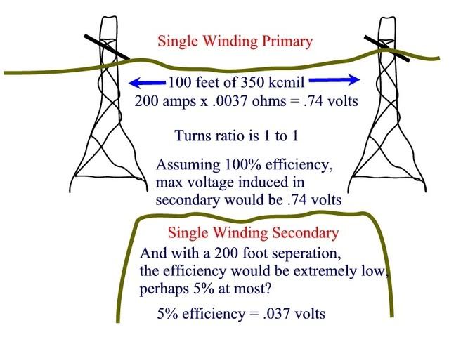
Diagram should say "volts" and not amps.
When you did your analysis of the voltage drop on the HV line versus the voltage drop in the coil, you suggested that the resistance drop in the primary limits the voltage that could be induced in the coil. This is not the case. Any current induced in the secondary would create a magnetic field which would result in a magnetic voltage drop on the primary. If the secondary were very well coupled to the primary, you would have a transformer and could induce lots of voltage in the secondary, at a cost of lots of voltage drop in the primary. You are correct in that with a 1:1 turns ratio the voltage on the primary is equal to the voltage on the secondary, but this is the magnetically induced voltage, and ignores any voltage drop.
I agree with you completely now that you mention that. The induction from one conductor to the other will certainly cause the impedance of the "primary" to be higher, which will cause a larger voltage drop than just the resistance of the wire. Of course, any significant voltage drop would be felt on the power lines as a drop in voltage at the load end. Now, at 200 feet between the transmission lines and the loop leaves very poor magnetic coupling indeed.
I belive that your diagram expresses why the coupling between the transmission lines and a random five foot coupling will be very weak. There will only be a slight difference in the flux cut by one side of the coil versus the other side, which is another way of saying that the net flux flowing through the coil would be extremely small, and thus a very small voltage induced in the coil.
Oops, maybe I don't understand what you mean up above in your first thought when you are talking about the flux in the center of the loop... because you obviously understand my point as expressed in the diagram. Could you further explain what you mean by flux at the center of the loop?
The only reason that you get high currents in this case is that you have a low voltage applied to a dead short.
Agreed, and is the reason I
have not totally discounted the phenomenon. The resistance of a #6 copper wire is going to be very very very low and it doesn't take much voltage to push current through it. On the other hand, we have to take into account the inductance of the loop too.
for most line configurations, there will be a significant 'rotating field' component, just like in an electric motor. This rotating field could induce voltage in a coil somewhere in the vicinity. It won't be a strong field, but if you set things up properly you might get something.
Understood. But I feel the majority of that rotating field will be between the conductors, not outside them. 200 feet away would render it almost nil?
I saw this in action at the Glen Canyon dam, while on a tour: power from the generators to the step up transformers was routed via conductors with perhaps 18" of separation. So you had three _large_ 'pipes' side by side carrying current from each set of generators to each set of transformers. At one point these pipes were vertical. Someone had placed an empty coffee can open side down on a spindle, between two of these pipes. The can was merrily spinning away, a very small mechanical load on a 'parasitic' induction motor.
Very cool, and totally believable, with some reservations about the nut who placed the thing between the conductors, and even more reservations about the security of the place, which would permit someone that close to those huge conductors in the first place. And what voltage were those conductors at? I am wondering about arcs and such for the guy brave enough to stick the pot in between.
Thanks for the input! :smile: I am really interested in this subject.