"Mystery Current" burns up cable splitters

Status
Not open for further replies.

steve66

Senior Member
Location
Illinois
Occupation
Engineer
crossman said:
So what we are comparing is the flux entering the loop versus the flux which is leaving the loop, and the difference is the flux that can cause a net voltage on the loop.

Yes, that is better said than I could of done. And I think Winnie is right about the concept of the amount of flux through the area being the same as the flux cutting the wire.

On your drawing with the loop of wire and the transmission lines, the flux through the loop should really be coming out of the page (or monitor) pointing toward you. And the flux above the transmission lines should be pointing into the monitor away from you (the flux circles the transmission wire line).

So when the flux is increasing, the lines of flux get denser, and they all cut the loop of wire by moving from the outside of the loop toward the center of the loop. So they are all causing the current flow to be in the same direction.

When the flux is decreasing, the flux gets thinner (the lines are farther apart), and the flux cuts the loop from the inside going outward.

If at two different times, we have a different amount of flux inside the loop, the difference in flux has to be the same amount of flux that has cut the loop.

I hope this makes some sense. I can visualize this a lot better than I can explain it.
Steve
 

crossman

Senior Member
Location
Southeast Texas
On your drawing with the loop of wire and the transmission lines, the flux through the loop should really be coming out of the page (or monitor) pointing toward you.[/qoute]

yeah, that was a pretty rough drawing!:smile:

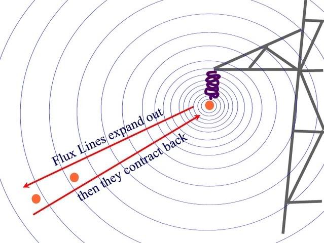
Here is a better one, viewed as a perpendicular cross section. This is my understanding of what the flux would actually be doing. There should be an arrowhead on each flux circle, all pointing the same way at a given time. And the arrowheads will alternate directions in the positive and negative portions of the cycle, and the flux lines will expand and contract for the positive half-cycle, then expand and contract for the negative portion of the cycle.

The two conductors at the bottom are the cross section of the loop. These conductors are connected together behind the page, and in front of the page.

crosstower.jpg


So when the flux is increasing, the lines of flux get denser, and they all cut the loop of wire by moving from the outside of the loop toward the center of the loop. So they are all causing the current flow to be in the same direction. When the flux is decreasing, the flux gets thinner (the lines are farther apart), and the flux cuts the loop from the inside going outward.

I have a different view of the situation. Notice in the diagram that the flux lines are cutting both conductors in the same direction. This is critical. At an arbitrary instant, let's say the voltage induced in the top loop is causing current to flow out of the page. At this same instant, the flux is cutting the lower part of the loop in the same direction, so the voltage in that loop is also causing the current to flow out of the page. Since these two voltage sources are connected together above the page, we have two voltages that oppose. The voltages will subtract.

Just to put some numbers in, assume the flux lines cutting the top loop create a 1 volt potential on that loop. Since the bottom of the loop is further away, let's say the slightly lessened flux creates a voltage of .99 in that wire. Couple the two together, and we get 1 volt - .99 volt = .01 volt.

That's the way I see it.

Edit for addition: If the scenrio of "mystery current" is true, can you imagine how much current would be flowing in all the loops of the tower? Since they are in such close proximity to the wires, there must be huge amps flowing in there.
 
Last edited:

crossman

Senior Member
Location
Southeast Texas
Here is the Mythbusters show where they actually tried to get the power from the transmission lines.

http://dsc.discovery.com/promos/videoplayer.html?dcitc=w03-001-ag-0001&clipID=52d1b75abbda8c22439a04b0ec69701808b1ed44

They didn't just use a single loop either, they said they used 3000 feet of wire. The more loops you make, the stronger the voltage should be, just like in a xfmr.

The PVC pipe frame that they used to hold the wire looked to be about 3 feet x 5 feet. A little math on the loop length with 3000 feet of wire gives us about 190 turns. Plus, the hoisted the thing up to within 16 feet of the lines. So 190 turns and 16 feet should be WAAAAY more powerful than 1 turn at 200 feet.

They said while the apparatus was sitting on the ground, it was producing .002 volts. When hoisted up in the air under the lines, it produced .008 volts. For a single turn, that is .000042 volts.

If this was a single loop of 16 feet length of #6 wire, the resistance would be .0079 ohms. A voltage of .000042 v and .0079 ohms gives .0053 amps.

I am seriously doubting "2 amps in the 5 foot loop of wire" thing.
 

crossman

Senior Member
Location
Southeast Texas
Here is another thought. (I guess I am seeming pretty obnoxious in all this, but I want to better understand the phenomenon and am hoping to provoke someone into setting me straight about the theory of how this could happen.

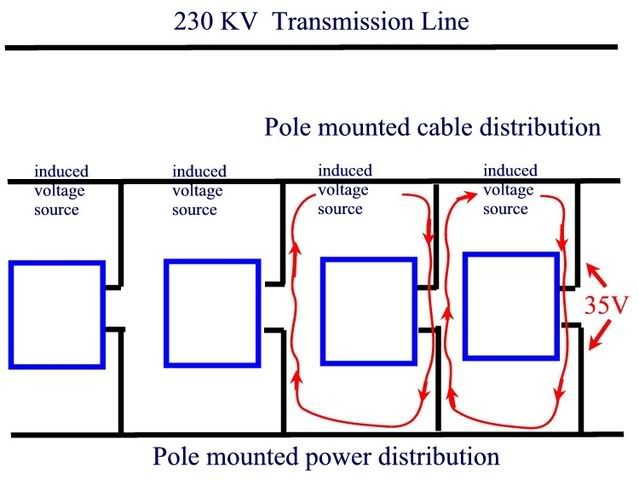
Here is a diagram similar to the one posted in the article about mystery current.

0000lineman.jpg


The article said there was 20 amps flowing from the cable tv wiring to the power distribution wiring. Well, look at an individual house. There are two induced power sources connected to the house. This is shown in red. Notice that the current from one source is opposite in direction from the current in the second source. These currents would cancel to some extent. Article said 20 amps and 35 volts. From induction? There are just too many things going against the scenario in my mind.

A couple days ago, I sent an email to the person who wrote the article, mentioning this thread and requesting more info. So far, no response. of course, the people responsible for the article certainly owe me nothing and it may even be in their best interest to avoid discussions such as these.
 

jghrist

Senior Member
The Mythbusters film is confusing. They say that they are connecting meters to measure current. It looks like they have used a clamp-on ammeter and a digital voltmeter. At the end, they say they have measured 8 millivolts. What are they measuring, current or voltage? If current, have they shorted the ends of the coil to allow current to flow? If voltage, are they measuring open circuit voltage across two ends of the coil? I assume that they are not measuring voltage to ground because all of the instruments are in their contraption up in the air.

I suspect that they were not measuring the open circuit voltage. Assuming their 3000' of wire is on a 3' x 6' frame, this is an area of 18 ft? with 167 turns. The transmission line looks like a 115 kV double circuit line. With typical phase spacings, and 200A in each phase, the flux density would be about ?=200 milligauss (rms) at a point 20' below the bottom phase. Using Faraday's Law:

V=-N?d?/dt

This would result in an open circuit voltage of about 2 volts.
 

crossman

Senior Member
Location
Southeast Texas
The transmission line looks like a 115 kV double circuit line. With typical phase spacings, and 200A in each phase, the flux density would be about ?=200 milligauss (rms) at a point 20' below the bottom phase. Using Faraday's Law:

V=-N?d?/dt

See post 62 above.

Are you considering that the voltage created in the bottom of the loops has to be subtracted from the voltage created in the top of the loops to find the net voltage on the coil?

My opinion: You need to do a V=-N?d?/dt calculation for the voltage in the top of the loops. Then do the same calculation for the voltage in the bottom of the loops. Subtract these two voltages. This gives the net voltage produced on the coil.

The only flux which would create a voltage in the loops is the difference between the flux at 20 feet below the power lines and the flux at 23 feet below the powerlines.

You say the flux density at 20 feet below the lines is 200 milligauss. What is the flux density at 23 feet below the power lines? Subtract that from the 200 milligauss, and there you have the flux density that can produce a net voltage in the coil.
 

jghrist

Senior Member
crossman said:
ghostbuster, I still need to be convinced that my post #66 is incorrect. Any info you can give on that would be appreciated.
Faraday's Law deals with a changing flux encircled by a loop or coil of wire. The voltage is induced between the ends of the coil by changing flux within the coil. It does not depend on a difference of flux between one side and the other. See http://hyperphysics.phy-astr.gsu.edu/hbase/electric/farlaw.html
 

crossman

Senior Member
Location
Southeast Texas
jghrist (or anyone else):

I see the info about Faraday's law. I am somewhat confused with it. If you could, please follow along through my reasoning about the following situation and show me where my logic is faulty. Seriously, if my thinking is wrong, I need to be corrected:

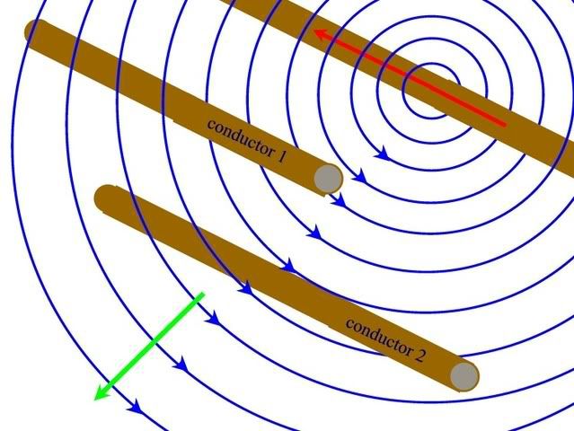
First Diagram Below:

Given:

1. The top conductor has a steadily increasing electron current flowing through it, shown with a red arrow (using electron flow theory). This will mimick the first quadrant of a sine wave current flow in the top conductor.
2. The flux lines (shown in blue) from the top conductor steadily increase outward (green arrow) from the conductor and arrowheads have been shown according to the left hand rule for flux around a conductor.
3. We have two other conductors, #1 and #2, parallel to the top conductor, and equally spaced from the top conductor.

flux1.jpg


Notice at this point we are not talking about loops. We have single conductors, #1 and #2.

My suppositions: Please step in and point out where I am wrong.

1. Cond #1 and cond #2 are cut by the same number of flux in any given time.
2. The direction of the flux cutting cond #1 is the same direction as cond #2.

Therefore:

3. The magnitude of voltage in cond #1 is the same as in cond #2.

4. The polarity of voltage in cond #1 is the same as in cond #2.

(From my reckoning of Fleming's Left Hand Generator Rule, the voltage in either conductor is trying to push electrons out of cond #1 and cond #2 towards us out of the screen.

Any mistakes so far?

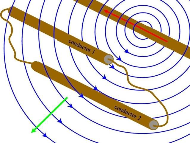
Next diagram:

Given: Take 2 wires and connect cond #1 to cond #2 to form a loop. The connecting wires are run perpendicular to the top conductor, meaning they are parallel to the flux lines, and therefore have negligible voltage induced in them, so do not affect the overall voltage of the loop. I am basing this on facts such as: In an AC alternator, the peak voltage is produced when the conductors cut the flux at 90 degree angles. No voltage is produced when the conductors are moving parallel to the flux lines.

I am not completely certain of this and perhaps is the downfall of my thinking. However, if voltage is induced in these two connecting wires, I will use the same argument above as concerning their voltages and polarities being equal and in the same direction (meaning either both up on the page, or down on the page).

flux2.jpg


5. Having connected cond #1 and cond #2 into a loop, we now have two series opposing voltage sources.

6. The voltages will cancel leaving no net voltage on the loop.

Anyway, see anything wrong?

I am certain that Faraday's Laws are correct, but there is a matter of properly using them. I can't help but think that the "rate of change of magnetic flux" which is the numerator in the formula at bottom right below is where the problem is concerning our situation above. This rate of change of flux has to be the net change of flux coming into the loop as compared to flux going out of the loop. In the case above, we have the exact same amount of flux leaving the coil as we have entering the coil at any given instant, therefore, the induced voltage is zero.

I see nothing about making cond #1 and cond #2 into a loop that would suddenly cause one of the conductors to reverse it's polarity compared to the other conductor. And if one of the voltages does reverse, how would you determine which one would reverse? Which way would the current flow in the loop?

fday.gif
 
Last edited:

ELA

Senior Member
Occupation
Electrical Test Engineer
crossman said:
Any mistakes so far?

Anyway, see anything wrong?

Your directional field lines have left me feeling a little Blue cause
I am right handed.
 

jghrist

Senior Member
crossman said:
jghrist (or anyone else):
1. Cond #1 and cond #2 are cut by the same number of flux in any given time.
2. The direction of the flux cutting cond #1 is the same direction as cond #2.

Therefore:

3. The magnitude of voltage in cond #1 is the same as in cond #2.

4. The polarity of voltage in cond #1 is the same as in cond #2.

(From my reckoning of Fleming's Left Hand Generator Rule, the voltage in either conductor is trying to push electrons out of cond #1 and cond #2 towards us out of the screen.
The problem as I see it is that you are assuming that the changing flux creates a voltage at a single wire because of the flux lines through the wire. What is the voltage with respect to? The flux is proportional to the number of lines. With your assumption, the thicker the wire, the more flux lines will pass through it. Does it make sense that more voltage would be induced in a fatter conductor?

I think you are confusing the electrostatic induction from the voltage on the power line with electromagnetic induction from the current. Electrostatic induction is like the power line and a parallel conductor form a capacitor.

It is the changing flux within an enclosed loop of wire that induces a current in the loop if it is continuous. If the loop is open, then there will be a voltage between the ends of the conductor. Faraday's law tells you how to calculate the voltage, but I have been unable to find a source that gives a formula for the current in a closed loop. Notice that the web site I linked to talks about the current being induced in the coil, but gives the formula for voltage.

I suppose that the current would be V/Z and that Z would include the conductor resistance and the inductance of the loop. The inductance would represent somehow the flux created by the current in the loop (which opposes the original flux per Lenze's Law).

This rate of change of flux has to be the net change of flux coming into the loop as compared to flux going out of the loop. In the case above, we have the exact same amount of flux leaving the coil as we have entering the coil at any given instant, therefore, the induced voltage is zero.
The same flux goes out of the loop as goes into it. In the case above, no lines of flux go through the loop so there is no voltage. If the loop were turned so that flux went through the opening, then if this flux changed, current would be induced in the closed loop. The flux changes sinusoidally in this case because the current causing it is changing sinusoidally. The rate of change of a sinusoid is another sinusoid, displaced by 90?. At the peak of the sinusoid, the rate of change is zero. The rate of change is maximum when the sinusoid crosses zero. You could also induce a current by moving a magnet through the coil to change the flux (making a crude generator).
 

rattus

Senior Member
As I see it:

As I see it:

We have a transformer here, a rather poor transformer though. The leakage reactance would be excessive, and that is what limits the current more than the impedance of the loop.

Leakage inductance/reactance is determined by the amount of flux which does not link the primary and secondary. It hurts my head to think about computing it.
 

winnie

Senior Member
Location
Springfield, MA, USA
Occupation
Electric motor research
crossman,

Your analysis as you have drawn things is correct. However you made a very important 'given', one that is not incorrect, but which is also not required by the problem. You said "3. We have two other conductors, #1 and #2, parallel to the top conductor, and equally spaced from the top conductor." This places a symmetry constraint on the result.

At any given moment in time, the lines of flux around the source conductor will be changing, and lines of flux will be expanding outward or contracting inward, cutting conductors #1 and #2. But with the conductors at the same distance from the source conductor, the same number of lines of force will cut each conductor, and the same voltage induced. Around a loop formed by conductors #1 and #2, the induced voltage will be zero.

But if we change the situation slightly, and require that the conductors be at different distance, then we will get a different result. When the current is in the source conductor is at its maximum, and the total magnetic flux is maximum, there will be some number of lines of force that thread between conductors #1 and #2. Any lines of force between the conductors clearly have had to 'cut' one conductor, but not the other, meaning that a different voltage will be induced on them, and a net voltage will be measured on the loop.

If you know the total flux threading between the two conductors, and you know the rate change of this quantity, you can calculate the voltage induced in the loop.

The formula in post 65 really should be given in vector form, and needs a term for loop area. The voltage induced in a loop is equal to the rate change of total flux threading that loop, where flux is given in Webers and rate change is per second.

If we know the flux density, the frequency, the area of the loop, and the number of turns, then we can calculate the total flux threading the loop, and the voltage induced in the loop. The voltage induced will depend upon how well the loop is oriented with the flux; with the axis of the loop pointed right at the source wire, no voltage will be induced, and with the plane of the loop containing the source wire, maximum voltage will be induced.

-Jon
 

jghrist

Senior Member
rattus said:
We have a transformer here, a rather poor transformer though. The leakage reactance would be excessive, and that is what limits the current more than the impedance of the loop.

Leakage inductance/reactance is determined by the amount of flux which does not link the primary and secondary. It hurts my head to think about computing it.
This is a good way for crossman to think of the situation. Consider a coil of wire wrapped around an iron core with all of the flux in the iron core. None of the flux goes through the conductor or outside the coil (ideal transformer with no leakage flux). The induced voltage in the coil depends on the changing flux in the core.

In the actual case, of course, there is a lot of flux outside the coil. This is irrelevant to the voltage induced in the coil. It just makes the transformer very inefficient because most of the flux created by the primary conductor does not produce any voltage in the secondary.

Maybe it hurts everyone's head to think about computing the leakage inductance. :mad: That's why I can't find any equations for the induced current either in my old textbooks or on the web.
 

crossman

Senior Member
Location
Southeast Texas
Thank you Winnie for the commentary. I agree completely with your assessment. As for the two conductors spaced equally from the powerlines, that was to prove a point about the voltage sources of the loop. I absolutely agree that placing one of the conductors further from the powerline will do exactly what you say. And that is what I have been trying to get across, that the difference in flux across the first conductor compared to the second conductor is what causes the net voltage. You expressed it well above, and you have validated my thinking.

Jghrist, I also appreciate your comments because they make me think.

I read jghrist's last post post #72 last night and did some serious thinking and research both on the internet, in physics texts, and in "electrician's texts.

I found something quite astonishing to me. First, let me give some background on myself: The vast majority of my electrical theory knowledge has come from self-study over the past 20 years (simply because I am interested in electrical theory). 27 years ago, I did spend 4 years in a DOL approved electrical apprenticeship that had schooling and OJT. The point is, my knowledge has come from textbooks which are written for electricians, not engineers or physicists. These would be texts such as Mileaf's Electricity 1-7 and Delmar's Standard Textbook of Electricity. I also have a couple of college Physics texts which I use to supplement my knowledge. I did go to college for a couple of years and have taken Calculus.

Now back to what astonished me. In the "practical" electrician's texts, inductance is always spoken of by "flux lines cutting conductors." But in the physics texts, it is termed "the rate of change of the flux density in the loop".

Throughout this thread, posts have referred to "the rate of change of the flux density in the loop." I didn't grasp the significance before (even though I commented on it and understood it but it just didn't make an impact until now). This concept struck me as strange, considering that my understanding of inductance is "cutting flux lines" and I have never considered "changing flux density in the loop".

But with Winnie's comments and my research and thought, I now understand that both concepts (cutting flux and changing flux density in loop) are EXACTLY the same thing.

So Physics and Engineering texts are much more mathematically rigorous, but much less instructive as to "why" things are, while the texts devoted to Electricians are much less mathematically rigorous, but try to explain "why" things are. In other words, "changing flux density in the loop" while being mathematically rigorous doesn't really explain why current would flow in the loop, but "flux cutting the conductor" informs me that the flux lines are reacting with the electrons in the conductor causing them to move.

Back to both methods being equivalent: Because flux lines are defined as "complete paths" in other words they must always curve to connect back to themselves, the only way that a flux line can get into or out of the loop to change the density is to cut across that loop. Therefore both ways to look at induction are equivalent.

So, it has done me some good to see things from the physics side. And I promise, those of you who have only seen induction as "change of flux density inside the loop" will get some good out of looking at "flux lines cutting conductors."

This is especially true for a single conductor, not a loop, moving through a magnetic field. Faraday's equation seems to not work, as there is no area which can be used in the equation. But "cutting flux" explains how a voltage can be induced in the single conductor. In "Physics for Scientists and Engineers", there is a statement:

"Figure 31.5 A straight conducting bar of length L moving with a velocity v through a uniform magnetic field B directed perpendicular to v. An emf equal to Blv is induced between the ends of the bar."

But, no expalantions, no mention of conductor cutting flux is given. The same exact scenario, in Delmars text, states:

"Whenever a conductor cuts through magnetic lines of flux, a voltage is induced into the conductor."

Great stuff, and a great learning experience!
 
Last edited:

crossman

Senior Member
Location
Southeast Texas
jghrist, bear with me here, there is alot to think about!:grin:

jghrist said:
The problem as I see it is that you are assuming that the changing flux creates a voltage at a single wire because of the flux lines through the wire. What is the voltage with respect to?

The voltage is in respect of one end of the wire to the other. Relative motion between a straight wire and a magnetic field will induce an emf in the wire, even without it being a loop. This is confirmed by many physics texts, electricians texts, and the internet. Here is what I wrote in post #76 concerning the matter:

This is especially true for a single conductor, not a loop, moving through a magnetic field. Faraday's equation seems to not work, as there is no area which can be used in the equation. But "cutting flux" explains how a voltage can be induced in the single conductor. In "Physics for Scientists and Engineers", there is a statement:

"Figure 31.5 A straight conducting bar of length L moving with a velocity v through a uniform magnetic field B directed perpendicular to v. An emf equal to Blv is induced between the ends of the bar."

But, no expalantions, no mention of conductor cutting flux is given. The same exact scenario, in Delmars text, states:

"Whenever a conductor cuts through magnetic lines of flux, a voltage is induced into the conductor."

The flux is proportional to the number of lines. With your assumption, the thicker the wire, the more flux lines will pass through it. Does it make sense that more voltage would be induced in a fatter conductor?

As I mentioned in post #76, I have always looked at induction as "flux cutting conductors" because of the texts I deal with. Do a google search on "induced voltage cut flux" or something similar, and you will find hundreds of references to what I am talking about. Flux cutting conductors is simply another way to look at induction, and is what I am familiar with. As for fatter conductors, I can't answer that. But cutting flux is still a viable way to view inductance. Check the internet...

From Delmar's Text: "In order to induce 1 volt in a conductor, the conductor must cut 100,000,000 lines of flux in one second. In magnetic measure, 100,000,000 lines of flux are equal to one weber."

I think you are confusing the electrostatic induction from the voltage on the power line with electromagnetic induction from the current. Electrostatic induction is like the power line and a parallel conductor form a capacitor.

I appreciate the thought, and I have not dismissed the possibility that capacitive current flow could have played a role in the original "Mystery Current" scenario. However, I do understand the difference between capacitance and inductance, and I am definitely talking about inductance when I speak of "flux cutting conductors".

It is the changing flux within an enclosed loop of wire that induces a current in the loop if it is continuous. If the loop is open, then there will be a voltage between the ends of the conductor. Faraday's law tells you how to calculate the voltage, but I have been unable to find a source that gives a formula for the current in a closed loop. Notice that the web site I linked to talks about the current being induced in the coil, but gives the formula for voltage.

Agreed. But as I mentioned in thread #76, there is another way to look at inductance - cutting flux. For the flux density in the loop to change, the flux lines must be either leaving or entering the loop, so the flux lines must cut across the loop. I will address this more concerning your post#75 where you talk about transformers and cores. I'll answer in a seperate post. Funny you mentioned transformers and cores because last night, I thought about the same exact thing you mentioned.

The same flux goes out of the loop as goes into it. In the case above, no lines of flux go through the loop so there is no voltage.

Agreed, but looking from my past education, there is another way to look at it: two equal voltages are induced in the two conductors because the exact same amount of flux is being cut by each conductor.

If the loop were turned so that flux went through the opening, then if this flux changed, current would be induced in the closed loop. The flux changes sinusoidally in this case because the current causing it is changing sinusoidally. The rate of change of a sinusoid is another sinusoid, displaced by 90?. At the peak of the sinusoid, the rate of change is zero. The rate of change is maximum when the sinusoid crosses zero. You could also induce a current by moving a magnet through the coil to change the flux (making a crude generator).

Agreed on the above. But again, for that flux density to change, flux lines must be cutting the loop to get into or out of the loop. I hope you do some thinking on this because having two ways to look at it is enlightening. Changing density versus cutting flux.

Thank you for the comments, I appreciate your interest! You are helping me to gain a better understanding. I hope you stay interested because it seems there aren't many people interested in this.:smile:
 

jghrist

Senior Member
crossman said:
The voltage is in respect of one end of the wire to the other. Relative motion between a straight wire and a magnetic field will induce an emf in the wire, even without it being a loop.
.... Flux cutting conductors is simply another way to look at induction, and is what I am familiar with.
After some thought, I see that you are correct. My problem was I was not thinking of the lines moving through the wire, but intersecting with the wire, when you talk about cutting the conductors. It's still easier for me to think about flux changing than fictitious lines moving, but I see your point. I've always thought of lines of flux being like the equal elevation lines on a topographic map, exept that they are lines of equal magnetic intensity.

How do you explain the flux in a transformer core that stays in the transformer core?
 

crossman

Senior Member
Location
Southeast Texas
jghrist said:
This is a good way for crossman to think of the situation. Consider a coil of wire wrapped around an iron core with all of the flux in the iron core. None of the flux goes through the conductor or outside the coil (ideal transformer with no leakage flux). The induced voltage in the coil depends on the changing flux in the core.

In the actual case, of course, there is a lot of flux outside the coil. This is irrelevant to the voltage induced in the coil. It just makes the transformer very inefficient because most of the flux created by the primary conductor does not produce any voltage in the secondary.

As mentioned, I did alot of research in my physics texts and on the internet last night, then laid in bed thinking about it all. The transformer with iron core was giving me problems just like jghrist said. Are the conductors cutting flux?

Then it hit me! Absolutely they are. Please follow along and give me your thoughts...

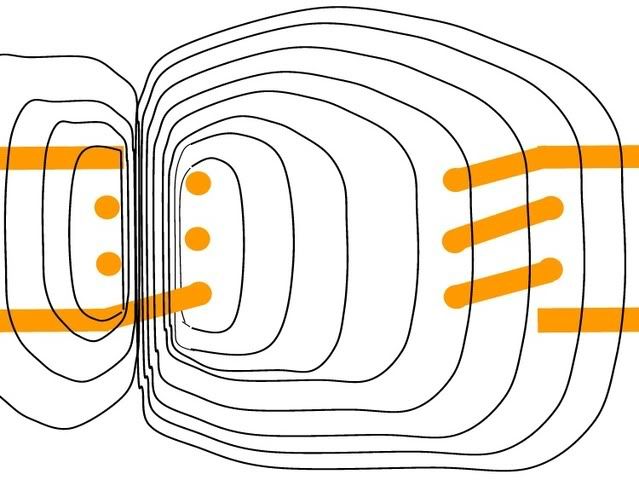
First, let's look at a xfmr with no iron core, just air:

Primary coil on left, secondary coil on right. Sinusoidal current flowing in primary. Flux lines are created by this current, they expand outward from the primary coil as the current increases and contract back toward the primary coil as current decreases.

Flux lines created by electron flow, as defined by any physics text, are always complete loops that can expand through space if the current creating them is increasing, and they can contract through space when the source current is decreasing. My point is, for a flux line to move from a given point A to a given point B, the flux lines must actually travel across the space between A and B. They can't just suddenly appear out in space away from the current flow. The must MOVE through the space first. Any arguments there?

transformernocore.jpg


Looking at the secondary on the right, we will notice a curious thing. The flux lines enter the secondary coil on the left side of the coil,, but then they also leave the secondary coil by exiting further right.

Two ways to look at it:

1. From a "changing flux density" perspective: we have flux entering from the left which increases the density, but we also have flux leaving the coil to the right, which decreases the flux density. So this fact will tend to cancel out the change in flux density... although as current in the primary increases, there will be somewhat more flux entering the coil than leaving, giving a relatively small voltage induced. (I guess this is where the term "flux leakage" comes from because flux is leaking out of the coil on the right hand side of the diagram.

2. From a "flux cutting conductors" viewpoint: We have a certain amount of flux cutting the left side of the turns of the secondary. This induces a voltage in the left side of the turns. Then the flux continues moving to the right and cuts the right side of the turns on the right side of the secondary. This cutting action induces another voltage in the right side of the turns which is opposite to that of the left side of the turns. This results in a relatively small net voltage in the coil. Now, as above, the flux lines are slightly more dense cutting the left side of the turns than what is cutting the right side of the turns. This difference in flux is equivalent to the changing flux density form above.

Both ways of looking at the situation are correct.

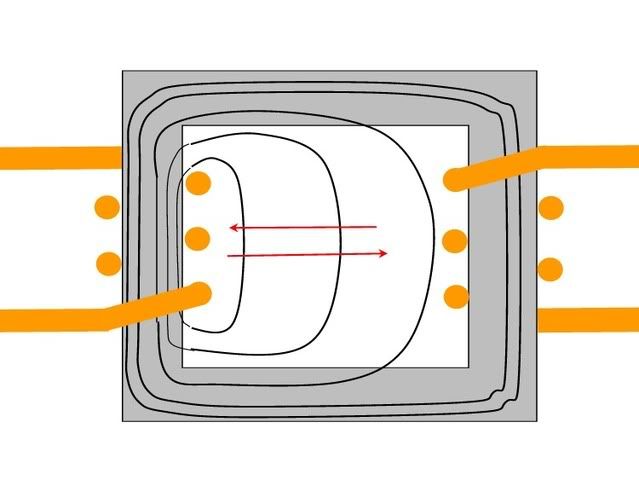
Now let's put an iron core in the xfmr:

On the left is the primary with sinusoidal current creating an expanding and contracting magnetic field. On the right is the secondary. Red arrows show the expansion and contraction. Black loops are the flux lines.

transformercore.jpg


Again, as the current in the primary increases, the flux lines start at the primary coil and expand outward. Now, some of this expansion must take place through the air inside the core. The flux lines cannot simply magically appear in the full rectangle of the iron core. No, they actually have to travel through space to get to the other side of the iron core. To increase the flux density in the core on the right hand side, the flux lines must expand and travel outward through the open space in the core to get there.

(As a thought experiment to prove my point, consider the iron core above to be 10,000 miles wide. All materials have reluctance which is simplistically "opposition to flux lines". Air has a higher reluctance than iron. However, 10,000 miles of iron has a higher reluctance than, say, 3 inches of air, so the flux lines from a typical current would not even get to the iron core on the right, they would just go through the air near the primary coil which would have less reluctance. Again, flux lines cannot magically appear at a given point in space. They have to move through space in an expanding loop to get to the given point.

Now, we can look at the iron core xfmr from 2 different perspectives:

1. Flux density perspective: We have flux lines entering the coil on the left hand side. These lines will increase the flux density in the coil. However, contrary to the air core xfmr, we have no flux leaving out the right side of the coil. Essentially we are trapping the flux inside the coil because the flux lines tend to stay inside the magnetic core once they get there. This will drastically increase the flux density inside the coil as compared to the air core coil. This will induce a correspondingly higher voltage in the secondary.

2. Flux lines cutting wire perspective: The flux lines from the primary travel from left to right across the center of the iron core, then enter the right hand side of the iron core. This moving flux will cut across the left side of the secondary turns, thereby inducing a voltage. Now, on the right hand side of the secondary, none of the flux is leaving the core to the right, so the right hand side of the coil is not cut by any flux. No voltage is produced on the right side of the coil. This leaves the entire voltage induced on the left side of the turns of the secondary as the net voltage on the coil.

Essentially, the iron core in the secondary is "shielding" the right hand side of the turns from experiencing any induced voltage because no flux is cutting the conductors on the right of the core. The right hand side of the coil cannot produce any voltage, so it cannot oppose the voltage that is induced on the left hand side.

Follow up: I am quite certain of all this, but certainly welcome comments, either agreeing or disagreeing. As for the textbooks, there are two different ways to look at inductance. Surely, if one of the ways was wrong, it would have been corrected by the science community? And if both ways are correct, they must be equivalent. In my mind, they are.:smile:
 
Last edited:

crossman

Senior Member
Location
Southeast Texas
jghrist said:
How do you explain the flux in a transformer core that stays in the transformer core?

Right up there^^^^!:grin:

I look forward to your thoughts. I am really getting alot from this, and I appreciate your interest.

After some thought, I see that you are correct. My problem was I was not thinking of the lines moving through the wire, but intersecting with the wire, when you talk about cutting the conductors. It's still easier for me to think about flux changing than fictitious lines moving, but I see your point. I've always thought of lines of flux being like the equal elevation lines on a topographic map, exept that they are lines of equal magnetic intensity.

I understand, because I had the opposite problem, I was having difficulty with the "flux density" thing. What puzzled me is how does flux in the center of the loop react with the loop? But I understand now... for the flux density in the loop to increase, the added flux had to come from outside the loop, cutting across the loop conductors.

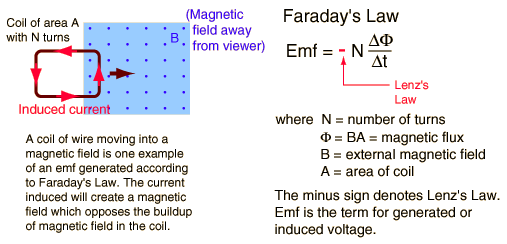
One other thing that was causing me confusion was Faraday's Equation as:

fday.gif


In the above equation, it entails the area of the loop, but nowhere does it account for various orientations of the loop to the magnetic field. But then I found the proper form of the equation which involves multiplying the magnetic flux by the cosine of the angle between the flux lines and a perpendicualr vector extending from the area of the loop. This helped me to understand the equation and relate it to "cutting of flux".

Very cool!:smile:

Edit: I reread Winnie' post and see that he already explained that the orientation of the loop is important as noted above with the cosine of the angle term.
 
Last edited:
Status
Not open for further replies.
Top