jghrist said:
This is a good way for crossman to think of the situation. Consider a coil of wire wrapped around an iron core with all of the flux in the iron core. None of the flux goes through the conductor or outside the coil (ideal transformer with no leakage flux). The induced voltage in the coil depends on the changing flux in the core.
In the actual case, of course, there is a lot of flux outside the coil. This is irrelevant to the voltage induced in the coil. It just makes the transformer very inefficient because most of the flux created by the primary conductor does not produce any voltage in the secondary.
As mentioned, I did alot of research in my physics texts and on the internet last night, then laid in bed thinking about it all. The transformer with iron core was giving me problems just like jghrist said. Are the conductors cutting flux?
Then it hit me! Absolutely they are. Please follow along and give me your thoughts...
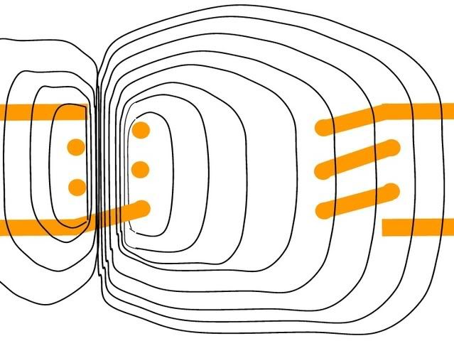
First, let's look at a xfmr with no iron core, just air:
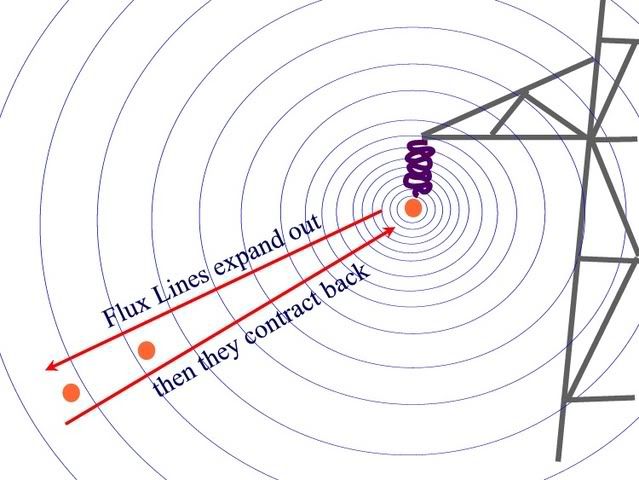
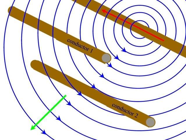
Primary coil on left, secondary coil on right. Sinusoidal current flowing in primary. Flux lines are created by this current, they expand outward from the primary coil as the current increases and contract back toward the primary coil as current decreases.
Flux lines created by electron flow, as defined by any physics text, are always complete loops that can expand through space if the current creating them is increasing, and they can contract through space when the source current is decreasing. My point is, for a flux line to move from a given point A to a given point B, the flux lines must actually travel across the space between A and B. They can't just suddenly appear out in space away from the current flow. The must MOVE through the space first. Any arguments there?
Looking at the secondary on the right, we will notice a curious thing. The flux lines enter the secondary coil on the left side of the coil,, but then they also leave the secondary coil by exiting further right.
Two ways to look at it:
1. From a "changing flux density" perspective: we have flux entering from the left which increases the density, but we also have flux leaving the coil to the right, which decreases the flux density. So this fact will tend to cancel out the change in flux density... although as current in the primary increases, there will be somewhat more flux entering the coil than leaving, giving a relatively small voltage induced. (I guess this is where the term "flux leakage" comes from because flux is leaking out of the coil on the right hand side of the diagram.
2. From a "flux cutting conductors" viewpoint: We have a certain amount of flux cutting the left side of the turns of the secondary. This induces a voltage in the left side of the turns. Then the flux continues moving to the right and cuts the right side of the turns on the right side of the secondary. This cutting action induces another voltage in the right side of the turns which is opposite to that of the left side of the turns. This results in a relatively small net voltage in the coil. Now, as above, the flux lines are slightly more dense cutting the left side of the turns than what is cutting the right side of the turns. This difference in flux is equivalent to the changing flux density form above.
Both ways of looking at the situation are correct.
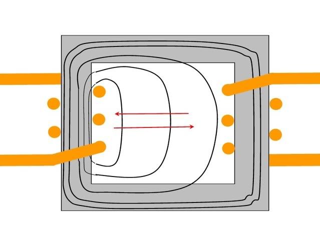
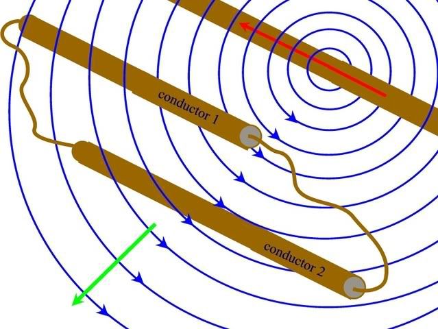
Now let's put an iron core in the xfmr:
On the left is the primary with sinusoidal current creating an expanding and contracting magnetic field. On the right is the secondary. Red arrows show the expansion and contraction. Black loops are the flux lines.
Again, as the current in the primary increases, the flux lines start at the primary coil and expand outward. Now, some of this expansion must take place through the air inside the core. The flux lines cannot simply magically appear in the full rectangle of the iron core. No, they actually have to travel through space to get to the other side of the iron core. To increase the flux density in the core on the right hand side, the flux lines must expand and travel outward through the open space in the core to get there.
(As a thought experiment to prove my point, consider the iron core above to be 10,000 miles wide. All materials have reluctance which is simplistically "opposition to flux lines". Air has a higher reluctance than iron. However, 10,000 miles of iron has a higher reluctance than, say, 3 inches of air, so the flux lines from a typical current would not even get to the iron core on the right, they would just go through the air near the primary coil which would have less reluctance. Again, flux lines cannot magically appear at a given point in space. They have to move through space in an expanding loop to get to the given point.
Now, we can look at the iron core xfmr from 2 different perspectives:
1. Flux density perspective: We have flux lines entering the coil on the left hand side. These lines will increase the flux density in the coil. However, contrary to the air core xfmr, we have no flux leaving out the right side of the coil. Essentially we are trapping the flux inside the coil because the flux lines tend to stay inside the magnetic core once they get there. This will drastically increase the flux density inside the coil as compared to the air core coil. This will induce a correspondingly higher voltage in the secondary.
2. Flux lines cutting wire perspective: The flux lines from the primary travel from left to right across the center of the iron core, then enter the right hand side of the iron core. This moving flux will cut across the left side of the secondary turns, thereby inducing a voltage. Now, on the right hand side of the secondary, none of the flux is leaving the core to the right, so the right hand side of the coil is not cut by any flux. No voltage is produced on the right side of the coil. This leaves the entire voltage induced on the left side of the turns of the secondary as the net voltage on the coil.
Essentially, the iron core in the secondary is "shielding" the right hand side of the turns from experiencing any induced voltage because no flux is cutting the conductors on the right of the core. The right hand side of the coil cannot produce any voltage, so it cannot oppose the voltage that is induced on the left hand side.
Follow up: I am quite certain of all this, but certainly welcome comments, either agreeing or disagreeing. As for the textbooks, there are two different ways to look at inductance. Surely, if one of the ways was wrong, it would have been corrected by the science community? And if both ways are correct, they must be equivalent. In my mind, they are.:smile:
 That's why I can't find any equations for the induced current either in my old textbooks or on the web.