Neutral sharing

Status
Not open for further replies.
Re: Neutral sharing

Bob i wish it was like that here but it just isn't.If it was i would pay the fee and or take the test.If no one enforces a license then few bother to get one.I am working on correcting this,but only because i might start contracting again.There would be an exstreme shortage in this town if they started next week doing what your talking about.Im understanding your thinking,but this area really just doesn't care if they comply or not.Should you move here they would hire you because of your skills and not that piece of paper.Give me something to fight them with to enforce it,wages would go way up.

[ January 15, 2004, 11:54 PM: Message edited by: jimwalker ]
 
Re: Neutral sharing

Originally posted by dnbob:
I worked with a "master electrician" today, and he did not understand the concept of a 120/240 v. circuit. he knew it needed 2 hots, 1 neut., but did not understand why you need to have the ungrounded conductors on opposite phases. I understand why, but is there an article to better explain it to him?
I am an apprentice. Could someone please explain to me why the hots need to be on different phases? What would happen if they were put on the same phase?

Jason Rand
 
Re: Neutral sharing

Jason it is all about the 60 cycle sign wave.The oposite phases can share the neutral because only one phase at a time uses the neutral,They are 180 degrees apart.Not sure just what books would help you.Try local library,they should have some books on basics,will likely have some on AC systems.I was lucky in high school took up shop.The old man there took a liking to me and gave me lots of extra attention.
 
Re: Neutral sharing

Jason, on a single phase service, you have one winding that is tapped in the center with a common conductor. (we will call this the neutral)

If we connect one end (leg) to a 10 amp load and the other side of the load to the common conductor, each conductor, hot and common, both carry 10 amps, and the common is not a neutral.

If we connect two 10 amp loads from the same end of the winding to one common, the common is still not a neutral, but now carries 20 amps where each hot conductor only carries 10 amps.

Notice how they add together if connected on the same leg.


If we now take one 10 amp load and connect it to the other end of the winding, then connect both
to the common, which is now a neutral, each hot carries 10 amps and the neutral carries zero.


The ends of the winding are peaking at the same time but on opposite sides of the zero line so current on the neutral is zeroed out due to two different current flows. (directions)

In theory, if all is even on both loads, the neutral could be removed and the loads would keep working unaffected.

Roger
 
Re: Neutral sharing

Jason, on a single phase service, you have one winding that is tapped in the center with a common conductor. (we will call this the neutral)

If we connect one end (leg) to a 10 amp load and the other side of the load to the common conductor, each conductor, hot and common, both carry 10 amps, and the common is not a neutral.
[/QUOTE]

I think I follow so far. My only question at this point is one of terminology. Why do you say that the common is not a neutral? The reason this is somewhat confusing to me is that I am used to hearing the term 'neutral' refer to the white conductor connected to a lamp, receptacle, etc. But isn't it true that the hot and the neutral connected to a lamp, for example, both carry the same amount of current?


If we connect two 10 amp loads from the same end of the winding to one common, the common is still not a neutral, but now carries 20 amps where each hot conductor only carries 10 amps.


OK, those two 10 amp loads you are describing are in parallel, right? Otherwise the hot conductor would carry 20 amps just like the common. I just want to make sure I'm following you correctly.


Notice how they add together if connected on the same leg.


Yes. So this means that if you connected both hots to the same phase at the panel, the neutral would end up carrying twice the current that each hot was carrying. Which would be more than that conductor was rated for. Right? I guess what I'm wondering is, if the neutral was sized appropriately for the increased current, would a 240v dryer work if the two hot legs were on the same phase?


If we now take one 10 amp load and connect it to the other end of the winding, then connect both
to the common, which is now a neutral, each hot carries 10 amps and the neutral carries zero.


OK, so here's another related question. If the two phases of the panel were perfectly balanced so that the loads on each phase were drawing the same current at a particular point in time, does this mean that the neutral from the service drop would be carrying absolutely no current at all?
And so the ammount of current being carried on the neutral from the service drop will always equal the difference between the current on the two phases?


The ends of the winding are peaking at the same time but on opposite sides of the zero line so current on the neutral is zeroed out due to two different current flows. (directions)

In theory, if all is even on both loads, the neutral could be removed and the loads would keep working unaffected.


I think that makes sense. Thanks Roger.

Jason
 
Re: Neutral sharing

Originally posted by jimwalker:
Jason it is all about the 60 cycle sign wave.The oposite phases can share the neutral because only one phase at a time uses the neutral,They are 180 degrees apart.
Thanks for the response, Jim. What do you mean when you say "only one phase at a time uses the neutral"? It would seem from Roger's explanation that the neutral isn't being used (it isn't carrying current) at all if the loads on the two phases are equal.

Jason
 
Re: Neutral sharing

Jason, he is correct in that should there be 2 equal loads on phase A and phase B that the neutral is a zero.
Try it this way.On paper draw a service of 240 volts with a neutral in between 120/240
now draw 2 light bulbs 100 watts each in series,and connect them across the 240 volts.
Now everything is fine and each bulb has 120 volts across it.
from the neutral of supply draw a line to where the 2 bulbs joined.
This neutral draws no current.
Should you change the bulbs to say a 50 watt and a 100 watt ,the neutral now has some unbalanced current.And if you were to remove that neutral the voltage across the 50 watt would 160 volts and across the 100 you have 80 volts.
Hope i am helping and not confusing you.If so tell me and i will stop.
 
Re: Neutral sharing

Originally posted by jimwalker:

Should you change the bulbs to say a 50 watt and a 100 watt ,the neutral now has some unbalanced current.And if you were to remove that neutral the voltage across the 50 watt would 160 volts and across the 100 you have 80 volts.
Jim, isn't that the other way around? The voltage drop across the 50 watt bulb would be 80, and the voltage drop across the 100 watt bulb would be 160. Right?

Jason
 
Re: Neutral sharing

This is an area of Theory, which really requires the person(s) being taught, to have some sort of text reference(s) - which can be used to interpret the reply messages in a BBS message.

I like Roger's reply - as it definitely covers the 1? 3W system accurately.

In a Kind-of complex EE nerd way of explaining it, the Magnetic Flow in the Core (talking Net flow - as results of Primary Flux and Secondary Flux), will be flowing in a certain direction per ? Cycle, thus determines the direction for Secondary Current to flow.
If the Secondary Winding is Center Tapped (either physically, or a split coil setup in series with a tap at the series jumper), there will be ? the maximum Potential of the entire Winding found at the Center Tap point.
This explains the 240/120 VAC part. Same results for remaining half of Cycle.

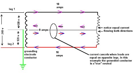
Currents balance across the Ungrounded Conductors, due to this being the "Actual Point Of Influence" from the Flux in the Core.
Simply, the Currents flowing through the connected loads are created as if the coil is only a 2 wire situation.
With equal loads across all L-C connection ("L-C" = Line-to-Common), this appears as if there are series loads of equal Impedance, connected between the coil's ends. Results = Currents flow L-L ("L-L" = Line-to-Line).
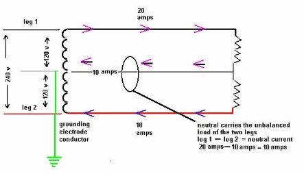
An imbalance will result in the "Odd" level of Current - which flows through the "Odd" level of Impedance, to be derived from the place of origin - the Center Tapped position of the coil. Results = Balanced Currents flow L-L, Imbalanced Currents flow L-C &/or C-L.

That's the "Crash-Course" techee way of saying it, which really is of no value to you, but may shed some light on the whole thing.

In reality, the whole thing has nothing to do with the type of currents - AC or DC! The same 3 Wire "Edison" Circuitry will work for AC and DC Power alike! Only on DC, there's two separate Power Sources conencted in Series Additive, with a tapped circuit conductor coming from the series jumper between the "+" of one source and the "-" of the other source.
The Common Center Tapped Conductor is both Polarities - "+" and "-".

I have Schematics of this baloney posted on-line if you (or anyone else) would like to view them.
Schematics of 3 and 5 Wire DC Systems, along with 1? Transformers having one, two and 3 taps off the Secondary. Also 1? Xformers with multiple Secondaries.
These drawings can be of great help when discussing this area of Theory.
Items may be found at ECN (Electrical Contractors Network) in the Technical Reference Section.
Can supply links if needed - just let me know either by posted reply, P.M. (Private Message) or direct E-mail (adst at pacbell dot net).

Lastly, while it's great that someone knows the tech reasons of operation for a common noodle, it's not the only judgement of any Electricians' abilities or level of expertness (is that a word???...hee hee hee).
Installing the stuff properly is of key importance.
A nice balance of both really makes me impressed!

Leaving the Soapbox...
Next Speaker, please take the 'box!

Scott35

p.s. - To Jason;

Jim, isn't that the other way around? The voltage drop across the 50 watt bulb would be 80,
and the voltage drop across the 100 watt bulb would be 160. Right?
Saw this after posting my message.

Jim is right. The Higher Impedance will need a Higher Voltage (Pressure) to push the Current through it.
The 50 Watt Lamp is in series with the 100 Watt Lamp, and thus results in the 50 Watt Lamp having a much higher Impedance than the 100 Watt Lamp - which will result in the higher Voltage being measured at the 50 Watt Lamp.
(Since these Lamps are Incandescent, we may say they are "Resistance Loads" and can swap the opposition from Impedance to Resistance - but this is another story...hee hee).

Also, just FYI - the 50 Watt Lamp will be twice as bright in this series scenario, than the 100 Watt Lamp.

End of extra fill!

Scott35

[ January 17, 2004, 06:47 PM: Message edited by: scott thompson ]
 
Re: Neutral sharing

Jason,
Why do you say that the common is not a neutral? The reason this is somewhat confusing to me is that I am used to hearing the term 'neutral' refer to the white conductor connected to a lamp, receptacle, etc. But isn't it true that the hot and the neutral connected to a lamp, for example, both carry the same amount of current?
we do refer to the white as a neutral in everyday conversation and this is accepted and is understood by trades people. Here is a graphic to show the answer to last question in your above paragraph.

:D )

OK, so here's another related question. If the two phases of the panel were perfectly balanced so that the loads on each phase were drawing the same current at a particular point in time, does this mean that the neutral from the service drop would be carrying absolutely no current at all?
Correct again. It would be an extension of the following graphic.

true_neutral.JPG


And so the ammount of current being carried on the neutral from the service drop will always equal the difference between the current on the two phases?
Correct again, you are doing a great job following .

unbalanced__neutral.JPG


Roger

P.S. Thanks for the earlier compliment Scott

edited for a spelling error.

[ January 17, 2004, 10:09 PM: Message edited by: roger ]
 
Re: Neutral sharing

Thanks, Scott, for the detailed explanation. Don't feel shy about getting up on your "soapbox" any time. The lightbulb example really had me puzzled for a while, but I think I understand it now. I was thinking that a higher wattage bulb would naturally offer more resistance, since it is the higher resistance of the element that makes it put out more light. Let's just say that it made sense in my own mind at the time.

Jason
 
Re: Neutral sharing

Roger, Thanks for the professional schematics. I was able to work through your explanation even without the diagrams, so those really drove home the points you were making.

Now, I just have one little remaining question. It seems that you think my question about putting both hots on the same phase is a separate discussion/argument, but if memory serves, that is precisely the question that started this thread in the first place. I still want to know, what would happen? If you beefed up the neutral to handle the current, could you make a 240v dryer work with the hots on the same phase? Would there be problems with the dryer? Or in other parts of the system?

I'm posing this question to Roger, or to anyone who has the time/patience to try and explain it to me. Thanks.

Jason
 
Re: Neutral sharing

Jason, thank you for complimenting my drawings, but if you're familiar with Electric Ed or Ronald Coleman, and as mentioned earlier Scott T, you know my drawings are at best amateurish. :)

Jason, if you look at 225.7 you will see where the NEC allows an oversized neutral (or common) conductor to serve more than one circuit.

The reason I said "conversation/argument" is that many of us don't see "eye to eye" on whether this is allowed elsewhere. ;)

Jason, keep up the good work.
icon14.gif


Roger

[ January 17, 2004, 09:47 PM: Message edited by: roger ]
 
Re: Neutral sharing

By Jason: If you beefed up the neutral to handle the current, could you make a 240v dryer work with the hots on the same phase? Would there be problems with the dryer? Or in other parts of the system?
If you connected a dryer with both the hots connected to the same phase you would not have the 220 volts to heat the heating element the timer, and light which runs on 120 volts would work but since the heating element uses 240 volts it would have both ends of the element just connected together and there would be no voltage across it.

Any multi-wire circuit that has the hot's connected to the same phase the neutral will carry the sum of the current of two circuits.

Any multi-wire circuit that has the hot's on opposite phases the neutral will carry the deferential of the current of the two circuits.

This is why there is a danger if a multi-wire circuit has the hot's put on the same phase it can over load the neutral.
 
Re: Neutral sharing

Originally posted by hurk27:
If you connected a dryer with both the hots connected to the same phase you would not have the 220 volts to heat the heating element the timer, and light which runs on 120 volts would work but since the heating element uses 240 volts it would have both ends of the element just connected together and there would be no voltage across it.
Thank you, Hurk. I can see that at this point to really answer my question I need to look at some schematics for a 240v dryer. I don't know if they are all wired basically the same way, or if there are a lot of different designs. I did find one schematic online, and it looks like all the 120 stuff (motor, timer motor, buzzer) comes off of one leg as it comes into the dryer. If I follow the wires through all those components, they are eventually connected to the neutral. The other leg comes into the dryer, goes through the heating element, and then connects to the junction where the 120 volt stuff is connected. So, in order to understand this system in a basic sort of way, I can think of this as a 3 wire system with two loads. One of the loads is the heating element, which is on the first line. The second line has no load on it. The second load consists of the motor, motor timer, and buzzer, which are all on the 'neutral'. So, what happens if both lines are on the same phase? Well, it would be like disconnecting the second line from the coil and then reconnecting it on the other end where the first line is connected. Having done this, the second line would act as a short circuit around the heating element. So, this is consistent with what you are saying, Hurk, that the heating element would get no voltage, but the other 120v components would work. If this is true, then it seems that even if we put both hots on the same phase, there would be no danger of overloading the neutral, since it would be carrying the exact same current that it is normally designed to carry. The only thing that would happen by putting the two hots (leading to a dryer) on the same phase is that the heating element wouldn't work at all. Cool. I think I get it. Do I?

Jason
 
Re: Neutral sharing

Hello all;

Just for the heck of it, decided to post a few Images of 1? Transformer Schematics, and two
Schematics of reference to 3-Wire DC systems.

These Schematics, along with others, may also be found at ECN's Technical Reference Section, using the
following link to the Section's Menu:

Menu For Technical Reference
Section


These 1? Transformer Schematics may be of interest, per the topic of this thread:

1phd5.gif


1phd4.gif


1phd6.gif


1phd7.gif


1phd8.gif


These drawings + additional drawings and simple descriptions, are from the
1 Phase Schematics - Part1
and the 1 Phase Schematics -
Part2
Pages.

Below are two references of 3 Wire DC systems:

3wdc1.gif


3wdc4.gif


The above drawings, along with other drawings & descriptions for 3 Wire DC systems,
may be checked out at the
Simple 3 Wire DC Circuits and
Systems
page, using the hyperlink provided in this sentence.

Additionally, the Simple 5 Wire
DC Systems
page can be of value, to see a more complex multiwire DC array!

Have fun!

Scott35

p.s. Sorry if the images are so large in file size, that it results in a verrrryyyy
ssslllllllooooowwwwwllllyyyyy loading page!
 
Hi. This is my first post. I am a builder and end up remodeling a lot. Hence, I do quite a bit of electrical work. I like doing my homework, and respect both electricity and craftsmanship too much to not try and do things in the best possible way, with the most possible understanding I'm capable of.

I found this a most excellent thread, particularly the exhange between Jason and Roger. Very clear expositions of 110/220 issues. Seems worthy of this bump up from 2004.

A further reiteration of the issue Jason asked seems to be this: In his dryer example, even if you reconnected one end of the heater to neutral (grounded conductor), and "combined" two 110v feeds from the same leg of your load center to feed the other end, you would not get 220v through the heater. You'd get 110v, just with the hot fed through double the wire. You just simply can never get 220v this way. You must wire 'line to line', ie. off the the two opposing legs of the load center, to get 220v.

Is my underatanding correct?

Thanks!

Sanaka
 
Status
Not open for further replies.
Top