You'd need to be a Scot to understand.......The internet of truth.
You'd need to be a Scot to understand.......The internet of truth.
Well I ain't from 'round there so...You'd need to be a Scot to understand.......
Not really although regional accents abound. An Aberdonian and a Glaswegian don't sound at all alike.Well I ain't from 'round there so...
Are you implying that the Scots can't all agree on the pronunciation?
That be L and C.Ok, back on topic
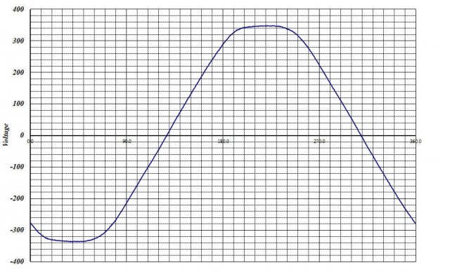
So it would seem when both X and C are in series, a type of "resonance" takes place?
https://www.youtube.com/watch?v=BPoDvcqqlDY
It is not pronouced "lock ness monster"? How is it pronounced?
So proper is eck-lee-fetch-in? or eck-lee-feck-in? How does she say it?
Loch Ness Monster of course.............
Except that they don't have it right.
The internet of truth.
Well I ain't from 'round there so...
Are you implying that the Scots can't all agree on the pronunciation?
I think you wil find that Robert Louis Balfour Stevenson made a pretty good fist of it.Hint: Neither Scots nor Americans speak English actually.
Awesome incite, thank
But how does on go about net power factor? Consider an HID lamp with a reactive ballast. Its essentially a resistor in series with a reactor, yet the power factor can vary all over the place.
I'm getting in on this late and didn't read all 19 pages, but an HID arc is not purely resistive, the current waveform of the arc is highly non-linear.
I think you wil find that Robert Louis Balfour Stevenson made a pretty good fist of it.
Samuel Clemens too.
And yes the British and Americans are different in different ways. I want to keep this thread on track, politely saying
Anyhow, why is it that ballasts are parallel X and C circuits and not series circuits?
As you vary X and C to get close to unity power factor the series impedance approaches zero, which is not much help in limiting the current through the lamp.
As you vary X and C to get close to unity power factor the series impedance approaches zero, which is not much help in limiting the current through the lamp.
You can calculate the impedances as shown but you can't add them up arithmetically - as simple numbers.I found this but still can't grasp total series impedance:
http://www.allaboutcircuits.com/textbook/alternating-current/chpt-5/series-r-l-and-c/
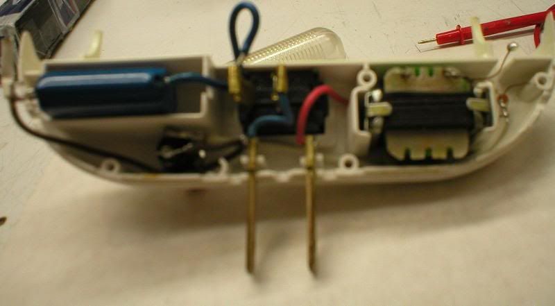
I do not see an inductor anywhere in the schematic. Nor in the picture.Here is what I have in mind (second picture in)
http://www.candlepowerforums.com/vb/showthread.php?260956-Fluorescent-to-LED-night-light-conversion
The ballast in this case us an capacitor and inductor in between the line. Perhaps not unit PF, but close. Yet even though its said this circuit would not provide impedance it still does somehow. It is this series circuit which puzzles me. The parallel aspect I understand from the equations posts (awesome help btw)
I do not see an inductor anywhere in the schematic. Nor in the picture.
Using a series capacitor to limit current is common for small loads and it does not provide anywhere near unity PF.
This, to the right: