Power factor

Status
Not open for further replies.

mbrooke

Batteries Included
Location
United States
Occupation
Technician
My undeertanding is that that was the original circuit, not the replacement capacitor input filter.
In any case, it is not clear to me just how the original circuit was wired.

It is the original circuit for the fluorescent tube. It goes prong>inductor>tube>starter>tube>capacitor>switch>prong. In this case the starter appears to replaced with a red push button most likely because it failed. I had a similar model night light 11 years ago and I can indeed confirm with 100% certainty the capacitor was in series with the circuit since I took it apart after it failed. In latter models the inductor was replaced with a 3 watt 22 ohm resistor and after that the glow tube starter were replaced with an electronic circuit. Eventually these were discontinued all together. But in any case I know with 100% certainty that series capacitor inductor ballasts exists. The other place Ive seen them (in real life) is in ultra cheap shop lights:

http://www.lighting-gallery.net/gallery/displayimage.php?album=657&pos=9&pid=79249


https://softsolder.com/2016/02/26/led-shoplight-conversion-fluorescent-fixture-teardown/
 

GoldDigger

Moderator
Staff member
Location
Placerville, CA, USA
Occupation
Retired PV System Designer
It is the original circuit for the fluorescent tube. It goes prong>inductor>tube>starter>tube>capacitor>switch>prong. In this case the starter appears to replaced with a red push button most likely because it failed. I had a similar model night light 11 years ago and I can indeed confirm with 100% certainty the capacitor was in series with the circuit since I took it apart after it failed. In latter models the inductor was replaced with a 3 watt 22 ohm resistor and after that the glow tube starter were replaced with an electronic circuit. Eventually these were discontinued all together. But in any case I know with 100% certainty that series capacitor inductor ballasts exists. The other place Ive seen them (in real life) is in ultra cheap shop lights:

http://www.lighting-gallery.net/gallery/displayimage.php?album=657&pos=9&pid=79249


https://softsolder.com/2016/02/26/led-shoplight-conversion-fluorescent-fixture-teardown/
The inductor has to be there to provide an inductive kick when the starter opens. Possibly the available inductor needed to be combined with the capacitor for some reason other than PF correction. I am sure the inductor and capacitor do not form a resonant circuit at 60Hz.
 

mbrooke

Batteries Included
Location
United States
Occupation
Technician
The inductor has to be there to provide an inductive kick when the starter opens. Possibly the available inductor needed to be combined with the capacitor for some reason other than PF correction. I am sure the inductor and capacitor do not form a resonant circuit at 60Hz.

But why are they in series?
 

GoldDigger

Moderator
Staff member
Location
Placerville, CA, USA
Occupation
Retired PV System Designer
But why are they in series?
To limit the current maybe??
A very small capacitor (high ZC) will dominate the current limiting at 60z while the small inductor will still have a high ZL at high frequencies to start the arc.

The operating PF will be a combination of capacitive (leading) and distortion (harmonics).
 

mbrooke

Batteries Included
Location
United States
Occupation
Technician
To limit the current maybe??
A very small capacitor (high ZC) will dominate the current limiting at 60z while the small inductor will still have a high ZL at high frequencies to start the arc.

The operating PF will be a combination of capacitive (leading) and distortion (harmonics).

So the inductor is only to provide a "kick" one the starter opens? That might explain why the choke is so small.
 

peter d

Senior Member
Location
New England
So the inductor is only to provide a "kick" one the starter opens? That might explain why the choke is so small.

Extremely cheap flourescents use the inductor to both start the lamp with a high voltage "kick" as well as limit the current once the lamp is operating. However this system is all but obsolete with modern electronics.
 

mbrooke

Batteries Included
Location
United States
Occupation
Technician
Extremely cheap flourescents use the inductor to both start the lamp with a high voltage "kick" as well as limit the current once the lamp is operating. However this system is all but obsolete with modern electronics.


Correct, this would be called a pre heat circuit found on very old fixtures and lower wattage versions up until recently. However ultra cheap shop lights stick a capacitor in series with the inductor... Food for thought. There might be a reason for that considering F40T12 tubes normally use an auto transformer ballast when operated at 120 volts using a preheat circuit due to the high operating voltage requirement. F15T8s and F20T12s require and lower operating voltage and use a simple choke when run at 120 volts preheat. Note I am not referring to F40T12 rapid start ballasts which omit the starter and use heater windings within the ballast to provide a few volts to the cathodes. The ones I have in mind are genuine preheats.
 

Sahib

Senior Member
Location
India
Mbrook:1)60Hz means iron core inductor, not air core inductor used.2)Series capacitor use in twin flourescent lamp is to avoid stroboscopic effect.
 

Besoeker

Senior Member
Location
UK
Mbrook:1)60Hz means iron core inductor, not air core inductor used.
Don't follow your logic in that.
Air-conductors can be, and often are, used at power frequencies.

alind01_zps1ac4278e.jpg


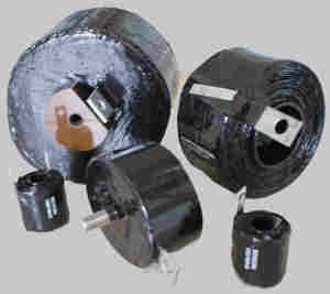
We used these for limiting di/dt in power electronics.
 

Besoeker

Senior Member
Location
UK
I used it with reference to florescent lamp discussed by mbrook. In old version florescent lamp with magnetic ballasts, iron core inductors are used; air core inductors are not practicable.
I was simply pointing out that air-cored chokes can be/are used at the 60Hz power frequency.
 

Sahib

Senior Member
Location
India
Air-conductors can be, and often are, used at power frequencies.

alind01_zps1ac4278e.jpg


We used these for limiting di/dt in power electronics.

As you say ''used these for limiting di/dt in power electronics'', it seems to imply ''i'' of higher frequency as the slope of ''i '' i.e di/dt increases with increase in frequency of ''i''.

What a self contradiction!
 

mbrooke

Batteries Included
Location
United States
Occupation
Technician
Mbrook:1)60Hz means iron core inductor, not air core inductor used.


I know, it is an iron core.

2)Series capacitor use in twin flourescent lamp is to avoid stroboscopic effect.


Correct, in twin tube rapid start ballasts. The shop lights I have in mind are a series inductor circuit running a single tube.
 

mbrooke

Batteries Included
Location
United States
Occupation
Technician

Sahib

Senior Member
Location
India
The shop lights I have in mind are a series inductor circuit running a single tube.
Then if the series capacitor is part of the original design, no problem. But if it is a field modification, check the lamp current. If it exceeds the design value, the lamp life would be shortened.
 

mbrooke

Batteries Included
Location
United States
Occupation
Technician
Then if the series capacitor is part of the original design, no problem. But if it is a field modification, check the lamp current. If it exceeds the design value, the lamp life would be shortened.


Why do you say the lamp life will be shortened?
 

Sahib

Senior Member
Location
India
Why do you say the lamp life will be shortened?
Introduction of a series capacitor in the lamp circuit with inductance will reduce the overall impedance presented to the power supply and if such an act is not part of the original design, it would likely increase the current through the lamp above its design value with consequent reduction in its rated life due to nature of tungsten filaments at the lamp ends.
 
Status
Not open for further replies.
Top