Series Voltage Drop All Inclusive

Status
Not open for further replies.

W@ttson

Senior Member
Location
USA
Hello All,

I would like to put the topic of series voltage drop in various types of three phase wiring arrangements for roadway lighting to rest. I have always had to look into this to get the right methodology, and I would like to get confirmation or explanation as to if my set up for the 4 different type of wiring methods and the associated formulas I have come across are correct or why they are not correct.

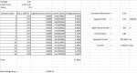
In the four arrangements I have a 480V/277V three phase system, in the different arrangements I explore the notion of currents canceling the neutral thus reducing voltage drop etc. I look at single phase across lines and single phase to neutral. When looking to do the series voltage drop for roadway lighting applications I look to use the correct formula, ie: VD=2*I*Z(effective)*L(oneway) or VD=1.732*I*Z(effective)*L(oneway)

Please look at the attached two pdfs for the wiring methods further explained and associated formulas listed.
 

Attachments

  • Different Arrangments for roadway lighting voltage drop.pdf
    73.4 KB · Views: 10
  • Different Arrangments for roadway lighting voltage drop - 2.pdf
    81.6 KB · Views: 10

W@ttson

Senior Member
Location
USA
Just to clear I wanted to see if anyone can confirm the equations found in the PDFs. Thank you
 

GoldDigger

Moderator
Staff member
Location
Placerville, CA, USA
Occupation
Retired PV System Designer
Which formula you use depends in part on whether the I used is line to line or line to neutral.
Also on whether you want to get the line to line or line to neutral VD.
With kind to line loads there is partial cancellation in the ungrounded wires as well as in the neutral.
 

Smart $

Esteemed Member
Location
Ohio
You diagrams just show three fixtures, each connected differently. To have series voltage drop, you need two or more of the same connection. Are you going to figure each section separately?
 

W@ttson

Senior Member
Location
USA
Im sorry, I should have included a bit more information in the files.

Each diagram is a different arrangment of how roadway light can be wired up in a 480/277VAC system. The "..." to the right of the fixtures indicates a continuation of the sequence. There is no set number of fixtures, could be 3,6,9,12 or what ever triplet you want. Each fixture is actually its own stand alone pole, i.e. one fixture per pole.

I know the general rule that Single phase VD uses the equation with the 2 and three phase uses the equation with the 1.732, however, what I am looking for are the subtle clarifications when wiring such as in what I show in arrangement 1. In arrangement 1 its a three phase system, however, each fixture is wired Line to Neutral. A-N, B-N, C-N. Now some might argue that you need to do it per phase and the calculation would need to be done using the equation with the 2 factor. Some might argue that since all three phases use the same neutral, the system must be looked at as a whole and the current in the neutral must be realized that it will be zero, therefore, the use of the "2" would be an over design since you won't need to worry about the return length. I choose one way to look at it and listed an equation I wanted to see everyone's thoughts on it.

I try to reason out all of the configurations that I show. Arrangement 2 = Single phase wiring, however, line to line connection. Again I say that it can be looked at as a three phase system since the loads are balanced (so again I used the 1.732).

This was sparked by looking at a DOTs sample calculations for roadway lighting. In it they showed a "480/240" where they wire the fixtures Phase to Neutral, and say that the voltage drop in the neutral can be disregarded.

Anyway, I look forward to the responses.
 

gar

Senior Member
Location
Ann Arbor, Michigan
Occupation
EE
151023-0949 EDT

spraymax6:

You need to understand the basics of whatever circuit you are working on. This should mean an understanding of the derivation of any equation you are working with. This also means a clear definition of all terms is required.

I don't have time at the moment to go into detail. But first consider a distribution system from an energy source to a balanced load at the far end of the distribution system. Make this system a 4 wire wye system and consider a balanced load of 3 kW in both a delta and wye configuration. Is there a difference in the voltage drop along a hot wire between the two types of load? Is there any difference along the neutral?

.
 

W@ttson

Senior Member
Location
USA
151023-0949 EDT

spraymax6:

You need to understand the basics of whatever circuit you are working on. This should mean an understanding of the derivation of any equation you are working with. This also means a clear definition of all terms is required.

I don't have time at the moment to go into detail. But first consider a distribution system from an energy source to a balanced load at the far end of the distribution system. Make this system a 4 wire wye system and consider a balanced load of 3 kW in both a delta and wye configuration. Is there a difference in the voltage drop along a hot wire between the two types of load? Is there any difference along the neutral?

.


I don't quite see the set up. A wiring diagram would be helpful.

All I am looking for in my diagrams in my post is for someone to simply agree or disagree with the equations used for each arrangement. I specify the load in each case and how it is connected to the distribution system. I am not sure how else I can detail it more. This is supposed to be general so that it can be adapted to any amount of loads etc you have. For example for arrangement 1 I have given the following information:

The source voltage and wiring: 480/277V 3Ph, 4 wire
I gave how each luminaire is tied to the source: Each one is tied Line to neutral. There is the same amount of fixtures on phase A as there are on B and on C. They all share the same neutral.
I gave my assumption as to why I am thinking that I should use VD=1.732*I*L*Z should be used.

All I am looking for is the following response:
Arrangement 1 Correct Formula?: Yes/No
Arrangement 2 Correct Formula?: Yes/No
Arrangement 3 Correct Formula?: Yes/No
Arrangement 4 Correct Formula?: Yes/No

If it is also not too much trouble, if the answer is no to any one of the arrangements I show in the PDFs in my original post, please list the variation of the VD equation you would use.

If a concrete example with concrete numbers is needed, I can provide a mock numbers on the number of lights etc, but what I think all is needed is how each light is wired to each phase.
 

Smart $

Esteemed Member
Location
Ohio
Whether to use the 2 multiplier on 3Ø L-N-connected loads depends on the likelihood of coincidental operation. If all the lights on all phases will be on or off at the same time (within reason for say photocell-controlled lighting), you can essentially disregard the neutral for basic calculations.

If you were to get uber technical about the neutral, you would have to calculate the drop of neutral current between fixtures. Let me explain. While balanced L-N load circuits have a net neutral current of 0 at the source and to the first fixture tap, after that there is current on the neutral between fixtures. There has to be or the lights won't work. What comes into play is that the current only has to travel through the distance necessary to cancel out. An oversimplification of this is all the current of the first fixture has to travel to the second and then half of that to the third, while half of the second travels to the first and half to the third, while half the third fixtures current came from the first fixture and half from the second. That's not uber, uber technical, because the progression would then evaluate to zero current between the third and fourth fixtures, which is not the case in the real world. The most comprehensive method uses network analysis.
 

W@ttson

Senior Member
Location
USA
Whether to use the 2 multiplier on 3Ø L-N-connected loads depends on the likelihood of coincidental operation. If all the lights on all phases will be on or off at the same time (within reason for say photocell-controlled lighting), you can essentially disregard the neutral for basic calculations.

If you were to get uber technical about the neutral, you would have to calculate the drop of neutral current between fixtures. Let me explain. While balanced L-N load circuits have a net neutral current of 0 at the source and to the first fixture tap, after that there is current on the neutral between fixtures. There has to be or the lights won't work. What comes into play is that the current only has to travel through the distance necessary to cancel out. An oversimplification of this is all the current of the first fixture has to travel to the second and then half of that to the third, while half of the second travels to the first and half to the third, while half the third fixtures current came from the first fixture and half from the second. That's not uber, uber technical, because the progression would then evaluate to zero current between the third and fourth fixtures, which is not the case in the real world. The most comprehensive method uses network analysis.

Smart $, Thank you, that is the type of thing I was looking for. I thought about that neutral current in between the fixtures, but then I said I don't want to get that deep into it. I might spend some time looking at that more, though now.

Thanks again for the response.

As for arrangement 2, I suppose the same would occur. If want to simplify the calculation and just lump the load at the end and think of it as a three phase, that is one way. However, if I want to look deeper and do a series voltage drop calculation, there will be drop in between fixtures and I would need to use the "2".
 

Smart $

Esteemed Member
Location
Ohio
Your equations aren't what I'm questioning most in reading your posts and evaluating your diagrams.

What I question most is your understanding of series voltage drop and its calculation. Let's use a two-wire three fixture circuit to give a basic example. If "i" is equal to the current of one fixture, the current from the source to the first fixture is 3i, while the current from the first fixture to the second is 2i, then from the second to the third is 1i.

The voltage drop is progressive from fixture to fixture, and while the lowest voltage is at the third fixture, the voltage drop in comparison to the the source voltage is less than indicated by your formulas if you use total current and total length. To use your formulas, you would have to evaluate the drop of each section of the circuit separately, then determine the total voltage drop by summing the drop of each section.
 

W@ttson

Senior Member
Location
USA
Whether to use the 2 multiplier on 3Ø L-N-connected loads depends on the likelihood of coincidental operation. If all the lights on all phases will be on or off at the same time (within reason for say photocell-controlled lighting), you can essentially disregard the neutral for basic calculations...


Just to make sure, if you wanted to keep the calculation simple, and disregard the neutral, you would still, however, use 1.732, correct?
 

W@ttson

Senior Member
Location
USA
Your equations aren't what I'm questioning most in reading your posts and evaluating your diagrams.

What I question most is your understanding of series voltage drop and its calculation. Let's use a two-wire three fixture circuit to give a basic example. If "i" is equal to the current of one fixture, the current from the source to the first fixture is 3i, while the current from the first fixture to the second is 2i, then from the second to the third is 1i.

The voltage drop is progressive from fixture to fixture, and while the lowest voltage is at the third fixture, the voltage drop in comparison to the the source voltage is less than indicated by your formulas if you use total current and total length. To use your formulas, you would have to evaluate the drop of each section of the circuit separately, then determine the total voltage drop by summing the drop of each section.

Yes, that is how I did it. I did it by hand first then I used EDR. Then I had someone check it and use Excel. Posted is the excel version. The problem that started all this, is I saw a lighting circuit and I said there is no way the voltage drop will be OK. So I did the series voltage drop calc to be able to get the most true result. Like I thought the voltage drop was astronomical. I now need to fix the other engineers lighting scheme. So I need to get as a precise answer as possible per phase.

Actual problem at hand:

There are about 84 fixtures. Fixtures are roughly balanced completely on all three phases. So there are 28 fixtures per phase. Each pole has two fixtures on it, therefore, there are 14 poles. Each fixture is 150W, therefore, there is 300W at each pole. Each pole utilizing the same phase is 150 feet apart ( each pole is 50 feet apart).

When the excel file was created to do the calc, since this was looked at as a per phase calc, 2*I*Z*L was used for the VD. I want to see if a little more can be shaved so want to see if 1.732*I*Z*L can be used since as you can see the voltage drop is horrendous and the fix is going to be costly.
 

Attachments

  • Temp_VD - Copy.JPG
    Temp_VD - Copy.JPG
    102.3 KB · Views: 5

W@ttson

Senior Member
Location
USA
Have you considered using L-L voltage fixtures. You'll always run into voltage drop problems at that distance and number using 120V fixtures.

Smart $, I wish, that's what I would have done. But I came on this project late in the game and its going to be constructed as shown on plans, no chance of changing the fixtures. Im going to have to call for another feeder to take on some of the load, but need to submit justifications, due to the big ticket price.
 

W@ttson

Senior Member
Location
USA
Yeah, so what ended up making me come on, is to see if the original designer could have assumed something I am not since the calc is sooo off. Is there anyway possible that the voltage drop isn't as bad as I am showing in the picture? Could he not have used 2 or 1.732? I am just second guessing myself at this point.
 

GoldDigger

Moderator
Staff member
Location
Placerville, CA, USA
Occupation
Retired PV System Designer
Yeah, so what ended up making me come on, is to see if the original designer could have assumed something I am not since the calc is sooo off. Is there anyway possible that the voltage drop isn't as bad as I am showing in the picture? Could he not have used 2 or 1.732? I am just second guessing myself at this point.
There is a good (bad) chance that he just thought "Line to neutral load, no neutral current, so one wire drop only. So a factor of 1." And then maybe used the line to line voltage to calculate the current from the wattage?
It is not correct to use the factor of 2 from the single phase calculation, nor the factor of 1.732 for L-L loads.
The drop in the neutral resulting from imbalance in each pole to pole run will only be for the current applicable to a single pole or two poles (1.732 times single pole) of load, never the cumulative current for 14 poles, so that neutral term will still be conveniently small.

Smart $ is trying to guide you on how to calculate segment by segment but still allow for substantial cancellation in the neutral, but you seem to be resisting that idea.
 
Last edited:

W@ttson

Senior Member
Location
USA
There is a good (bad) chance that he just thought "Line to neutral load, no neutral current, so one wire drop only. So a factor of 1." And then maybe used the line to line voltage to calculate the current from the wattage?


Golddigger, that puts me a little more at ease (in a way). I still need to bring this up with a clear outline to the higher ups on what the actually voltage drop is, if there is anyway it will work, and how to fix it for the least amount of money... We will see.

With the original PDFs what I was looking to do, was to generalize this problem into all different sort of ways that roadway lighting could be wired up, it somewhat of a guide, so that I can hand it off to someone in the future and say, follow this, if your fixture is 480 Single phase, do your series drop like this and use this equation for each segment, then tally up all voltage drops. I look to avoid situations like I am in now.

Thanks for your insights guys.
 

W@ttson

Senior Member
Location
USA
There is a good (bad) chance that he just thought "Line to neutral load, no neutral current, so one wire drop only. So a factor of 1." And then maybe used the line to line voltage to calculate the current from the wattage?
It is not correct to use the factor of 2 from the single phase calculation, nor the factor of 1.732 for L-L loads.
The drop in the neutral resulting from imbalance in each pole to pole run will only be for the current applicable to a single pole or two poles (1.732 times single pole) of load, never the cumulative current for 14 poles, so that neutral term will still be conveniently small.

Smart $ is trying to guide you on how to calculate segment by segment but still allow for substantial cancellation in the neutral, but you seem to be resisting that idea.

In the calculation, the 14 poles are all on the same phase. In total there are 42 poles. The voltage drop in the calculation picture above is per segment. For example the first light in Phase A has 41Amps, running in that segment, the distance is 150 feet from the source and the resistance per 1000ft is .19 ohms. This yeilds: 2*41.176*.15*.0285=2.3471Volts. Now the last pole on phase A is 150feet from the pole preceding it and since it is the last pole it only has 2.9412 Amps of current in that segment. Therefore, the VD = 2*.15*.0285*2.94 = 0.1676V.... Adding all of the voltage drops from the first to the last together yields 17.60V. What would you say that the voltage drop in phase A would be?
 
Status
Not open for further replies.
Top