Series Voltage Drop All Inclusive

Status
Not open for further replies.

GoldDigger

Moderator
Staff member
Location
Placerville, CA, USA
Occupation
Retired PV System Designer
Zero current in one pole to pole segment means zero voltage drop on that pole to pole segment (e.g 2-3, 5-6, etc. It does not mean zero voltage drop from the service to the last pole in that segment.
You have an I**2R energy loss in two out of three runs in each group and that energy loss must be reflected in an overall voltage drop from the service point.
The neutral voltage drop in each group of 3 will be 1.732 times the voltage drop for one pole's worth of lights over the distance between two poles. I think... That or just the single voltage drop without the 1.732 factor.
 

gar

Senior Member
Location
Ann Arbor, Michigan
Occupation
EE
151024-0632 EDT

spraymax6:

Why are you working at 120 V? Why even consider a wye distribution system? A delta load eliminates the cost of a neutral wire, it can still be a wye source. A half mile of wire at 120 V is a lot of cost.

.
 

GoldDigger

Moderator
Staff member
Location
Placerville, CA, USA
Occupation
Retired PV System Designer
Zero current in one pole to pole segment means zero voltage drop on that pole to pole segment (e.g 2-3, 5-6, etc. It does not mean zero voltage drop from the service to the last pole in that segment.
You have an I**2R energy loss in two out of three runs in each group and that energy loss must be reflected in an overall voltage drop from the service point.
The neutral voltage drop in each group of 3 will be 1.732 times the voltage drop for one pole's worth of lights over the distance between two poles. I think... That or just the single voltage drop without the 1.732 factor.
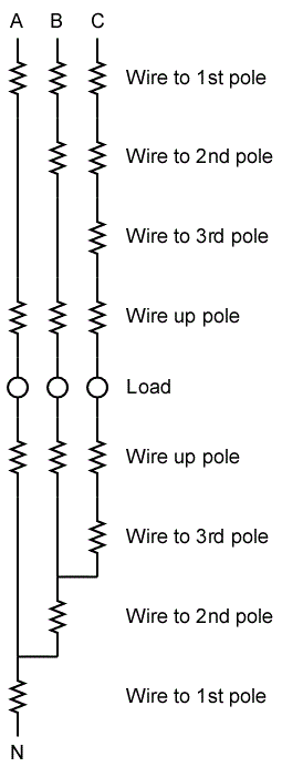
Too late to edit, but although my concept remains unchanged my numbering was backwards.
The zero current run involving poles 1, 2, and 3 is from supply to pole 1. Not from 2 to 3.
Major rectocranial inversion.
The principle remains the same in that pole 3's neutral terminal is at a different potential from the supply neutral. And the pole 6 neutral will be offset from the pole 3 neutral by the same amount. And so on down the line to the end.
 

Smart $

Esteemed Member
Location
Ohio
Too late to edit, but although my concept remains unchanged my numbering was backwards.
The zero current run involving poles 1, 2, and 3 is from supply to pole 1. Not from 2 to 3.
Major rectocranial inversion.
The principle remains the same in that pole 3's neutral terminal is at a different potential from the supply neutral. And the pole 6 neutral will be offset from the pole 3 neutral by the same amount. And so on down the line to the end.
You're attempting to reconcile an imperfect model with a more accurate one. Nothing wrong with that, but I'd like to see you follow through to the last pole and tell us how much difference there is.
 

Smart $

Esteemed Member
Location
Ohio
151024-0632 EDT

spraymax6:

Why are you working at 120 V? Why even consider a wye distribution system? A delta load eliminates the cost of a neutral wire, it can still be a wye source. A half mile of wire at 120 V is a lot of cost.

.
Asked and answered...
Have you considered using L-L voltage fixtures. You'll always run into voltage drop problems at that distance and number using 120V fixtures.

Smart $, I wish, that's what I would have done. But I came on this project late in the game and its going to be constructed as shown on plans, no chance of changing the fixtures. Im going to have to call for another feeder to take on some of the load, but need to submit justifications, due to the big ticket price.
 

W@ttson

Senior Member
Location
USA
Zero current in one pole to pole segment means zero voltage drop on that pole to pole segment (e.g 2-3, 5-6, etc. It does not mean zero voltage drop from the service to the last pole in that segment.You have an I**2R energy loss in two out of three runs in each group and that energy loss must be reflected in an overall voltage drop from the service point.The neutral voltage drop in each group of 3 will be 1.732 times the voltage drop for one pole's worth of lights over the distance between two poles. I think... That or just the single voltage drop without the 1.732 factor.
GoldDigger, So my sketch with the voltage drop between two of the three was legs of betrayal per group was accurate? In the end the difference is not that big but I would just like to get the correct concept down.
 

gar

Senior Member
Location
Ann Arbor, Michigan
Occupation
EE
151024-2126 EDT

My analysis of the voltage drop per 150 ft, 50 ft between poles.

Assumptions:
1. Neutral resistance per 50 ft = 0.000,95 ohms = R1.
2. The single phase current magnitude per light pole is 300/(0.85*120) = 2.941 A. Call this I1.
3. The neutral voltage drop over a range of 3 poles is the same for each group of 3 poles independent of how close the pole group is to the source.
4. For the effect of the unbalanced neutral current on neutral voltage drop we only need to study the last 150 feet. That is the last group of 3 poles.

The last 50 ft of neutral has a drop of V3 = R1*I1 = 0.000,95*2.941 = 0.00279 V, and a power dissipation of 0.00822 W.

The next 50 ft has a drop of V2 = R1*1.732*I1 = 0.000,95*1.732*2.942 = 0.00483 V, and power is 0.0246 W.

The first 50 ft has a drop of 0 V because the three currents balance out to 0 A.

Total power dissipation in 100 ft is 0.00822+0.0246 = 0.0328 W. Total resistance for 100 ft is 0.0019 ohms. Calculated voltage drop magnitude from power dissipated = sq-root of (0.0328*0.0019) = 0.0079 V.

Calculating the vector sum of the two 50 ft segement voltages produced comparable results.

The total voltage drop for the 14 groups of 3 50 ft groups is 14*0.0079 = 0.111 V. Practically this is negligible compared to 120 V.

Check my math.

..
 

Smart $

Esteemed Member
Location
Ohio
151024-2126 EDT

My analysis of the voltage drop...

....

The total voltage drop for the 14 groups of 3 50 ft groups is 14*0.0079 = 0.111 V. Practically this is negligible compared to 120 V.

Check my math.

..
I was with you right up until the end. Your total voltage drop statement is making the same assertion as GoldDigger, i.e. there is an accumulative neutral voltage drop from the source to the last pole.

What is the net voltage change of each 3 pole group? (e.g. voltage between the neutral connections at the source and at pole 3, then from pole 3 to pole 6, and so on through pole 39 to pole 42)
 

gar

Senior Member
Location
Ann Arbor, Michigan
Occupation
EE
151025-1150 EDT

Smart $:

For each 150 ft group of lights, 3 poles and the conductors leading to them, there is a neutral voltage drop of 0.0079 V RMS magnitude at a composite vector angle of K over that 150 ft length. That same neutral voltage drop magnitude and vector angle exists for each of the 14 150 ft groups. Thus, 14*0.0079 gives us the total neutral voltage drop.

All other increasing currents in the hot wires balance each other in the neutral and do not create an increasing neutral voltage drop as you approach the source.

When you view the problem from a power dissipation perspective it is clear there has to be a summation of voltage drops.

.
 

GoldDigger

Moderator
Staff member
Location
Placerville, CA, USA
Occupation
Retired PV System Designer
It took me awhile to get comfortable with the idea, but if you do not limit yourself to resistive loads or allow more than one phase per pole AND do not require the same current on each load you can come up with a scheme where the voltage drops all cancel out, leaving no net voltage shift from one end to the other.
The approach of adding up resistive losses does not work in this situation because some "voltage drops" are actually bringing the neutral voltage back toward the source potential.
Here is a very artificial example:
You have two poles, A and B, with the same length of wire from source to A as from A to B.
Use 120/240 three wire single phase.
Place a load on pole A that draws current I from L1.
Place a load in pole B that draws current I/2 from L2.
The neutral VD at B will be zero even though power is being dissipated in both runs of wire.
Note that since there is a net current of I/2 in the neutral at the source thus particular scheme cannot be extended to more than 2 poles. But with adjustments to the load current at each pole you can always work out a zero VD at one specified pole (i.e the last one.)
 

Smart $

Esteemed Member
Location
Ohio
151025-1150 EDT

Smart $:

For each 150 ft group of lights, 3 poles and the conductors leading to them, there is a neutral voltage drop of 0.0079 V RMS magnitude at a composite vector angle of K over that 150 ft length. That same neutral voltage drop magnitude and vector angle exists for each of the 14 150 ft groups. Thus, 14*0.0079 gives us the total neutral voltage drop.

All other increasing currents in the hot wires balance each other in the neutral and do not create an increasing neutral voltage drop as you approach the source.

When you view the problem from a power dissipation perspective it is clear there has to be a summation of voltage drops.

.
Look at it like this. Every third neutral segment has zero current, zero voltage drop. Can you remove these segments without affecting the voltage at and current through each load?

Viewing the problem from a power dissipation perspective makes no difference to me. The only thing that matters is the change in voltage from source to the last neutral connection.
 

gar

Senior Member
Location
Ann Arbor, Michigan
Occupation
EE
161025-1624 EDT

Smart $ and GoldDigger:

The original statement of the problem was that each light was the same as any other light. Thus, from a gross perspective load is balanced. Fully balaned at the beginnibg of each 150 ft group.

As soon as the neutral segment with zero net current is opened, then the remaining center point of three lamps is no longer at zero potential relative to the neutral point at the source.

.
 

Smart $

Esteemed Member
Location
Ohio
161025-1624 EDT

Smart $ and GoldDigger:

The original statement of the problem was that each light was the same as any other light. Thus, from a gross perspective load is balanced. Fully balaned at the beginnibg of each 150 ft group.

As soon as the neutral segment with zero net current is opened, then the remaining center point of three lamps is no longer at zero potential relative to the neutral point at the source.

.
The problem is the model used. If the loads are identical and fully balanced at the source neutral, then there is no change in voltage between source neutral and the neutral connection at the end of the first group, and this cascades through the second to last group.

What you are doing is what I brought up to GoldDigger, and that is, you are attempting to reconcile the imperfect model with a more accurate model. In this reconciliation, you are forgetting that the first segment will not be zero current, zero voltage change.

Evaluate the first group by itself (i.e. only three poles) as a network...

Network.gif
 

GoldDigger

Moderator
Staff member
Location
Placerville, CA, USA
Occupation
Retired PV System Designer
The problem is the model used. If the loads are identical and fully balanced at the source neutral, then there is no change in voltage between source neutral and the neutral connection at the end of the first group, and this cascades through the second to last group.

What you are doing is what I brought up to GoldDigger, and that is, you are attempting to reconcile the imperfect model with a more accurate model. In this reconciliation, you are forgetting that the first segment will not be zero current, zero voltage change.

Evaluate the first group by itself (i.e. only three poles) as a network...

Network.gif
The problem that I have is your premise that because there is zero current in the neutral at the source there cannot, therefore, be a non-zero voltage drop from end to source. There are still unbalanced currents at various points along the way.
What you can say is that the net current from the last group of three has no effect on the voltage in any other group of three. That is both clear and correct.
It is also true that the VD between the first pole and the source is zero. Fine. But the VD from third pole to source is not zero. I hope you can agree on that.

The zero current at the start of each group does mean that to calculate the voltage drop from the third pole to the source you do not have to (or want to) consider any contribution from downstream groups.

But if the calculation for one three pole group shows a voltage drop between the third pole and the source, then that same drop will be repeated for each group down the line.
As shown in the approximate but close calculation the VD for one group is small, so the VD for 14 groups is 14 times small, which is still small compared to the VD in ungrounded wires, which is proportional to 14 squared.
 

Smart $

Esteemed Member
Location
Ohio
The problem that I have is your premise that because there is zero current in the neutral at the source there cannot, therefore, be a non-zero voltage drop from end to source. There are still unbalanced currents at various points along the way.
What you can say is that the net current from the last group of three has no effect on the voltage in any other group of three. That is both clear and correct.
It is also true that the VD between the first pole and the source is zero. Fine. But the VD from third pole to source is not zero. I hope you can agree on that.

The zero current at the start of each group does mean that to calculate the voltage drop from the third pole to the source you do not have to (or want to) consider any contribution from downstream groups.

But if the calculation for one three pole group shows a voltage drop between the third pole and the source, then that same drop will be repeated for each group down the line.
As shown in the approximate but close calculation the VD for one group is small, so the VD for 14 groups is 14 times small, which is still small compared to the VD in ungrounded wires, which is proportional to 14 squared.
I'm not saying there is no neutral voltage drop in a real circuit.

But there is also no real model of the situation in this thread which exhibits a zero current segment.

When you choose to use an imperfect model as in this thread, the connotation that goes with that acceptance is that you also accept the associated fallacies. You are choosing to mix models and conclude as you see fit.
 

GoldDigger

Moderator
Staff member
Location
Placerville, CA, USA
Occupation
Retired PV System Designer
The only way imperfection in the model is the assumption that the downstream loads draw the same current even though the voltage is lower. That has no significant effect on the calculation of the neutral voltage drop as being non zero.
The idealized model does show a non zero voltage drop along the neutral. And you can approximate the idealized situation as well as you want in the real world if you make each of the loads a regulated constant current load instead of either resistive or constant power.
 

Smart $

Esteemed Member
Location
Ohio
The only way imperfection in the model is the assumption that the downstream loads draw the same current even though the voltage is lower. That has no significant effect on the calculation of the neutral voltage drop as being non zero.
The idealized model does show a non zero voltage drop along the neutral. And you can approximate the idealized situation as well as you want in the real world if you make each of the loads a regulated constant current load instead of either resistive or constant power.
I think we have to go back to the beginning of this thread. The imperfect model was suggested by ignoring the neutral voltage drop. We can step around that as many ways as you'd like... but it always amounts to no neutral voltage drop. :angel:
 

GoldDigger

Moderator
Staff member
Location
Placerville, CA, USA
Occupation
Retired PV System Designer
The imperfect model actually assumed no voltage drop in the ungrounded leads either, therefore all luminaires would draw the same current. On that basis we calculated the voltage drop on the hot leads. As long as the deviation from the assumption is small that is a perfect valid way to get an approximation.
I really do not see why you do not accept that there is a neutral voltage drop measurable at the third pole (in a three pole only system).
 

Smart $

Esteemed Member
Location
Ohio
...
I really do not see why you do not accept that there is a neutral voltage drop measurable at the third pole (in a three pole only system).
I do accept it... when the model permits. :slaphead:

Here you are saying one imperfect method is perfectly acceptable... yet another method no more, no less deviant in the big picture is not. :thumbsdown:
 

GoldDigger

Moderator
Staff member
Location
Placerville, CA, USA
Occupation
Retired PV System Designer
I do accept it... when the model permits. :slaphead:
OK. I therefore propose a model which uses constant current loads.
In that model there is a cumulative neutral drop increasing with every three pole set you add. And the calculated voltage offset (hard to call it a drop in a three phase system) is very close to what you would measure in a real system.
FWIW, in either a real or idealized system you can all but eliminate the neutral offset by rotating the phase order in each three pole group.
That is:
First set poke 1 is on A, pole 2 on B, pole 3 on C.
Next group uses B, C, A.
Third group uses C, A, B.
Every nine poles the neutral voltage at the last pole is equal to the neutral voltage at the source.
 
Status
Not open for further replies.
Top