Single Phase current draw for a 3 phase output VFD: technical discussion

Status
Not open for further replies.

gar

Senior Member
Location
Ann Arbor, Michigan
Occupation
EE
170521-0920 EDT

This thread is a derivative of a closed thread, and the title of this thread probably does not directly indicate the purpose of the original thread.

As I have previously said several times the original question was about the use of a particular 3 phase VFD with an associated motor and fan in a different application where only 1 phase power is available.

It is fairly self-evident that feasible power output will be determined by the diode rectifiers and/or filter capacitor. There are time constant factors, including load needs, that enter into the analysis. The power output requirements vary with time. When peak power needs occur (outside doors are opened) what peak power limitation (based on the end user's needs or desires) can be tolerated? Does perfect exhausting have to occur? These questions in relation to how hard can the VFD be loaded in 1 phase operation for short times will determine if the application will work.

Diode heating, capacitor heating, and ripple would seem to be the critical items to discuss.

.
 

mike_kilroy

Senior Member
Location
United States
So what about power factor, couldn't lower power factor on the VFD output side cause the above to not hold?

Cheers, Wayne

No. Output pf is 100% handled by the bus caps. It does not even get to the ac vfd input side. Displacement PF input is effectively 1.0 on ac input to vfd regardless of motor pf at any given time.

Sent from my SM-G900V using Tapatalk
 

wwhitney

Senior Member
Location
Berkeley, CA
Occupation
Retired
No. Output pf is 100% handled by the bus caps. It does not even get to the ac vfd input side. Displacement PF input is effectively 1.0 on ac input to vfd regardless of motor pf at any given time.
I agree with all of the above, so perhaps I am misunderstanding where Io is being measured. I thought it would be at the VFD - motor connection, so it would reflect motor power factor.

Cheers, Wayne
 

Smart $

Esteemed Member
Location
Ohio
That's incorrect. Possibly not your field of expertise. No problem.

I know I've done this before. Maybe you will understand it this time.
Call the three phases A, B, and C. Call the diodes in the top half of the Bridge A+ etc and those in the bottom A- etc. Current conducts first from A+ to B- then from A+ to C-.
Only two devices at any one time. If the DC is reasonably smooth/continuous each device conducts for 120 degrees.

Draw the circuit out. A+ and A- cannot conduct at the same time.
Okay. Now this I agree with to a point. It is the first contradictory reply that you've made with me that makes any sense. And I only get it out of you when I basically make a statement without thinking it through beforehand.

That said, I believe the correct statement should have been "3Ø current could be flowing through up to 3 diodes concurrently." Note the statement I highlighted in the quote of your reply. Dependent on the DC bus voltage, current could be flowing through both B- and C- diodes at the same time. This will occur where the DC bus voltage plus 2x diode bias voltage is less than A to B and A to C instantaneous voltages. It is only when the DC plus bias voltage exceeds the "crossing" voltage does the number of concurrently conducting diodes get reduced to two.

So, with this not being my field of expertise, I do have a basic understanding of what happens. :D
 

Smart $

Esteemed Member
Location
Ohio
I agree with all of the above, so perhaps I am misunderstanding where Io is being measured. I thought it would be at the VFD - motor connection, so it would reflect motor power factor.
No, you are not misunderstanding. And you bring up a valid point. A power factor being exhibited on the motor conductors is imminent. Recommended-for-VFD motors have improved power factor characteristics, but not so much that we can totally disregard it. :happyno:

Anyway, that's why I preferred to state the relationship as Pi>Po... as it takes power factor out of the equation. Ii/Io > 1.732 is simply a generalization with power factor correction built in. We've already heard that conversion losses raise the 1.732 factor. Well, motor power factor lowers the elusive factor.
 

Besoeker

Senior Member
Location
UK
No, I am not!
Indeed you are.
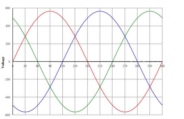
Look at the waveforms....
Justthreephase01_zpsbf2acfae.jpg


Specifically the period for which one phase is more positive than the other two. For as long as that persists the diodes in the other two phases will be reverse biased. And won't conduct.
Can you not see that?
 

Smart $

Esteemed Member
Location
Ohio
Indeed you are.
Look at the waveforms....
Justthreephase01_zpsbf2acfae.jpg


Specifically the period for which one phase is more positive than the other two. For as long as that persists the diodes in the other two phases will be reverse biased. And won't conduct.
Can you not see that?
Yes, the "+" diodes of the other two phases will be reverse biased... but the "–" diodes of the other two phases will be forward biased and will conduct. It's the only way the forward-biased "+" diode(s) will conduct.

Look in your diagram at the range of 60 to 120°. The only way the "+" diode connected to the red phase is going to conduct is if the "–" diodes connected to the green and blue phases also conduct.
 

Smart $

Esteemed Member
Location
Ohio
They do. Just not at the same time.
The red phase peak current occurs in phase with its voltage. All three lines must conduct, especially at the "–" crossing of the green and blue phases for there to be a peak at that point in time (90° in your diagram).
 

Besoeker

Senior Member
Location
UK
The red phase peak current occurs in phase with its voltage. All three lines must conduct, especially at the "–" crossing of the green and blue phases for there to be a peak at that point in time (90° in your diagram).
You just don't get it. Only two diodes conduct at any one time.
Accept and move on.
 

mivey

Senior Member
You just don't get it. Only two diodes conduct at any one time.
Accept and move on.
Wait! Wait! We have narrowed it down from a 60-120 degree window to some nanosecond or something exactly at 90 degrees. I can't believe you are being so frivolous! :D
 

junkhound

Senior Member
Location
Renton, WA
Occupation
EE, power electronics specialty
For clarity, a diagram of just 2 diodes.

If there is any decent sized DC link capacitor, there is not even a few nanoseconds of junction reverse recovery where more than 2 diodes conduct.

diodeschem.jpg
diodes.jpg
 

gar

Senior Member
Location
Ann Arbor, Michigan
Occupation
EE
170521-1714 EDT

In Besoeker's plot:

+R conducts thru -B and not +-G from 30 to 90, then +R conducts thru -G and not -+B from 90 to 150. At this point +R stops conducting.

At 150 +R stops conducting, and +B picks up the positive conduction.

+B conducts thru -G and not +-R from 150 to 210, then +B conducts thru -R and not -+G from 210 to 270. At this point +B stops conducting.

From this you can extrapolate to see what happens in the last 1/3 of the cycle.


Something I have not previously mentioned is that because of inductance in series with each diode there are short times at the transition points where the turning off diode remains on slightly longer.

.
 

Smart $

Esteemed Member
Location
Ohio

For clarity, a diagram of just 2 diodes.

If there is any decent sized DC link capacitor, there is not even a few nanoseconds of junction reverse recovery where more than 2 diodes conduct.
Increase the load and/or decrease the capacitance until you only get one hump per cycle per diode, such as the graph posted by gar (actually I'm assuming that's one hump per cycle in his image).
 

mike_kilroy

Senior Member
Location
United States
Yes.
For both you and Mivey.
Simple example.
On no load, a typical cage induction motor runs at about 30% FLC. Say 30A for a 55kW, 400V motor. The input current in such circumstances is very much lower. Certainly under 10A.

WRONG.

You know better than posting that! Why do this? You confuse those who might believe your nonsense comment!
 
Status
Not open for further replies.
Top