Single Phase Inverters on 208 3 Phase

But as I understand it, there is still a difference in behavior between a 3 phase inverter and 3 AC-coupled single phase inverters. In that in the 3 phase inverter the single phase subunits would share a common DC bus, so they'd each use 1/3 of the available power to jointly create a balanced output. While the 3 separate single phase inverters would have separate DC inputs and may not be able to jointly create a balanced output.

Agree.
Also, a single-phase inverter's instantaneous AC output current (and therefore also the currents drawn by the output transistors from the DC bus) will be small near the zero crossings of the grid voltage waveform. And so the capacitors on the DC side will have to be large enough to prevent this significant variation in current draw from causing excessive ripple on the DC bus voltage, which could then produce distortion of the current waveform or other problems.

On a 3-phase inverter, the lowest instantaneous current draw by the output transistors from the DC bus will be √3/2 ≈ 0.866 of the peak current draw. This smaller variation in the current draw will reduce the amount of DC bus ripple voltage and/or capacitor size compared to a single phase implementation.
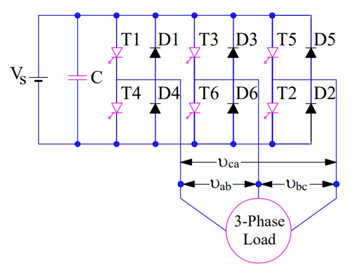
A simplified schematic with a 3-phase PV inverter:

1708713660946.png
 
Thanks again for the comments. In my last post, I failed to sufficiently explain the switching required for correct control of current flow through the three legs. After a little research, I found someone who provided drawings and an explanation of the process. Do the following photos and explanation properly define the timing of switching of current through the three legs for the first 240 degrees?

If this is accurate, please help me understand how three individual inverters, each connected to a pair of legs, can do the same switching among all three legs, or accomplish the same thing in a different manner.
equivalent-circuit-for-step-I-and-II-of-three-phase-bridge-inverter.jpg
Step-I is the first 60° with current flowing into switches 1 and 5, into legs a and c, into leg b and back through switch 6.
Step-II is 60° to 120° with current flowing into switch 1 through leg a, into legs b and c, and returning through switches 6 and 2.

equivalent-circuit-for-step-III-and-IV-of-three-phase-bridge-inverter.jpg

Step-III is 120° to 180° with current flowing into switches 1 and 3, into legs a and b, into leg c and returning through switch 2.
Step-IV is 180° to 240° with current flowing into switch 3, into leg b, into legs a and c, and returning through switches 2 and 4.

Taken from, "Three Phase Bridge Inverter Explained"
 
If this is accurate, please help me understand how three individual inverters, each connected to a pair of legs, can do the same switching among all three legs, or accomplish the same thing in a different manner.
Is your concern specific to the case of (3) single phase inverters connected L-L on a Wye source? Or does it extend to the case where the source topology and the inverter topology match?

Does it help you to know that if you are provided with (3) conductors A B C, such that the voltages A-B, B-C, and C-A are all equal in magnitude, but that for any two different pairs, the phase offset is 120 degrees, there's no way to tell from just those voltage waveforms whether the upstream source is a Delta or a Wye?

Cheers, Wayne
 
Is your concern specific to the case of (3) single phase inverters connected L-L on a Wye source?
Yes, my present concern is single phase inverters connected L-L on a Wye source.
Or does it extend to the case where the source topology and the inverter topology match?
I'm not sure what you mean and how source and inverter topology could match. I do have different concerns with 3 single-phase inverters connected to a Delta configuration.
Does it help you to know that if you are provided with (3) conductors A B C, such that the voltages A-B, B-C, and C-A are all equal in magnitude, but that for any two different pairs, the phase offset is 120 degrees, there's no way to tell from just those voltage waveforms whether the upstream source is a Delta or a Wye?

Cheers, Wayne
No, that doesn’t help. My concern is related to the current required to flow in each leg of the Wye secondary to induce the correct voltage and current into the primary. The 3-phase inverter accomplishes that by opening and closing switches such that it controls the switching of current from A-N into N-B AND into N-C, continuing to switch as needed through the rest of the cycle.

A single-phase inverter connected to A-B can only control current through A-N and N-B. I don’t see any way for a single phase inverter to send current into A-N into N-B and N-C, then allow A-N current to decrease while N-B increases.
 
This is the same point that you keep getting stuck on.

You are quite correct that a single phase inverter cannot simultaneously have decreasing current on A-N and increasing current on B-N. With a single inverter connected A-B there is only one current and the inverter created A-N current must exactly match the inverter created B-N current. (Except, of course for sign, which depends on your sign convention.)

What is getting you stuck is that THIS DOESN'T MATTER.

In the situation of a single 1 phase inverter connected L-L on a wye system, this single AC current waveform will have a phase angles offset from the grid created voltage waveforms. This results in a power factor and loss of capacity.

In the situation of 3 balanced 1 phase inverters, connected delta to a wye system, the sum of currents from each pair of inverters connected to each transformer terminal will balance, creating current in phase with the L-N voltage.

The individual single phase inverters do not and do not have to match the separate phase angles of the L-N coils they are connected to. All that matters is that the inverter output matches the L-L voltage that it directly sees.

Jonathan
 
No, that doesn’t help.
OK, but if you accept that 3 delta-connected single phase inverters work efficiently on a delta source, then that observation proves that they will work efficiently on a wye source, Since you can't tell the difference just given the 3 line conductors. I agree that may seem a bit mystifying and you'd still want to work out the details, but it helps to know what the answer will be ahead of time.

My concern is related to the current required to flow in each leg of the Wye secondary to induce the correct voltage and current into the primary.
Stop right there. No voltage is induced in the primary by these inverters. The grid is up and it sets all the voltages in the entire system. All you can look at is what currents the inverters create.

A single-phase inverter connected to A-B can only control current through A-N and N-B. I don’t see any way for a single phase inverter to send current into A-N into N-B and N-C, then allow A-N current to decrease while N-B increases.
It can't, although that wasn't your latest question. Your latest question was about the composite behavior of 3 separate single phase inverters delta connected, not just one single phase inverter.

Cheers, Wayne
 
Yes, my present concern is single phase inverters connected L-L on a Wye source.

I'm not sure what you mean and how source and inverter topology could match. I do have different concerns with 3 single-phase inverters connected to a Delta configuration.

No, that doesn’t help. My concern is related to the current required to flow in each leg of the Wye secondary to induce the correct voltage and current into the primary. The 3-phase inverter accomplishes that by opening and closing switches such that it controls the switching of current from A-N into N-B AND into N-C, continuing to switch as needed through the rest of the cycle.

A single-phase inverter connected to A-B can only control current through A-N and N-B. I don’t see any way for a single phase inverter to send current into A-N into N-B and N-C, then allow A-N current to decrease while N-B increases.
Unless you have a single phase inverter that is wired phase-to-neutral, most single phase inverters that are grid-following, follow the interphase voltage to generate power. They have an internal phase-to-neutral voltage sensor, but this is only to confirm that the grid is within spec, and isn't feeding a grid with faults. And which spec, is a setting you can select through the firmware.

If set for 120/240V split phase, a single phase inverter produces its power across the 240V that is measured across the two lines. The neutral is just an instrumentation neutral. Some use the neutral for powering internal power supplies.
 
please help me understand how three individual inverters, each connected to a pair of legs, can do the same switching among all three legs, or accomplish the same thing in a different manner.
OK, we've been over this before, but let's try again.

Typing sinewaves is hard, so when I type 100 ∠ 30, I mean the sinewave with magnitude 100 RMS, and which peaks at time 30 degrees (which is 30/360 of 1/60 of a second into the cycle). In a previous post, I gave you the algebraic formula for that sinewave, and you can type that into a graphing program to see the graph.

On a 208Y/120V secondary of a transformer, we have:

V(A-N) = 120 ∠ 0
V(B-N) = 120 ∠ 120
V(C-N) = 120 ∠ 240
V(B-A) = 208 ∠ 150
V(C-B) = 208 ∠ 270
V(A-C) = 208 ∠ 30

These voltages are fixed by the main source, our inverters do not and cannot change them.

What does the 3 phase wye-connected inverter do? If the total power output is 3600W, it puts out currents in phase with each L-N voltage:

I(A-N) = 10 ∠ 0
I(B-N) = 10 ∠ 120
I(C-N) = 10 ∠ 240

Here I'm suppressing a minus sign that comes from the inverter being a source rather than a load; as long as I do that consistently, it doesn't matter, it's just a choice of convention.

What do the three single-phase delta-connected inverters do? If the total power output is 3600W, each one is putting out 1200W, which at a voltage of 208V is 1200/208 = 5.77A. Then the three inverters put out currents in phase with the L-L voltages:

I(B-A) = 5.77 ∠ 150
I(C-B) = 5.77 ∠ 270
I(A-C) = 5.77 ∠ 30

Now we want to compare this situation with the previous situation. We can do this by looking at each node A, B, C, and comparing the total current going into that node in the two cases. I'll just do node A, as the other comparisons are the same, just rotated by 120 degrees.

In the first case, we have current going into A only from N, and I(A-N) = 10 ∠ 0.

In the second case, we have current going into A both from B and from C, so we need to look at I(A-B) + I(A-C). And I(A-B) = - I(B-A) (changing the sense of direction introduces a minus sign. That means in the second case, the current going into A is I(A-C) - I(B-A) = 5.77 ∠ 30 - 5.77 ∠ 150

Now finally we have to add (or rather subtract) two waveforms. Carultch made you a very nice Geogebra resource on visualizing how to do that back in post 154: https://forums.mikeholt.com/threads...rs-on-208-3-phase.2579133/page-8#post-2899046

The answer to the calculation is 5.77 ∠ 30 - 5.77 ∠ 150 = 10 ∠ 0. Which exactly matches the first case!

Cheers, Wayne
 
...

No, that doesn’t help. My concern is related to the current required to flow in each leg of the Wye secondary to induce the correct voltage and current into the primary.
What does that have to do with your application when the grid is inducing the correct voltage on the primary?
Also, what do you mean by the 'correct' current? I think there's a correct voltage, but current depends on what the loads draw.

A single-phase inverter connected to A-B can only control current through A-N and N-B. I don’t see any way for a single phase inverter to send current into A-N into N-B and N-C, then allow A-N current to decrease while N-B increases.
How about three phase-locked single phase inverters? How about one single-phase inverter and a grid?
We have agreed that a single-phase inverter can't create three phases through a transformer, but what does that have to do with your application? You are not trying to do that.

Let me offer an analogy for how this thread keeps going. Imagine three people in a canoe: one paddling on the left, one on the right, and the third steering in the back. We want them to paddle the canoe in a straight line. You keep saying "The guy on the left makes the canoe turn to the right, so how can the canoe go in a straight line?" And we keep saying "Well, the other two people's paddling also matters, they can keep the canoe going straight while the guy on the left keeps paddling." And then you say "But if we just look at the guy on the left, the boat turns." And we say "But you can't just look at the guy on the left, that isn't everything that's going on!" And you say "But if we just look at the guy on the left..." In post #282, you essentially said "I can understand how one guy who paddles on all sides can keep the boat straight, but not a guy who only paddles on the left." But in your application there's still other people in the boat.
 
What is getting you stuck is that THIS DOESN'T MATTER.
Yes! Voltage at the point of interconnection is determined by the grid connection, not the inverters, and if the current is unbalanced, no one cares as long as the POCO is OK with it, and they always have been for the systems like this that I have designed. If the the current difference to Vd makes the voltage a little different at the terminals of the inverters, again, no one cares.

To restate: I have designed many systems with single phase inverters connected to three phase services, both phase to phase (mostly) and phase to neutral, and they all performed as designed. They were mostly built years ago before smaller three phase inverters were commonplace, but they worked fine. VA in = VA out.

To quote Shakespeare, this thread is much ado about nothing.
 
... If the the current difference to Vd makes the voltage a little different at the terminals of the inverters, again, no one cares...
Unless, of course, the Vd were to push the voltage the inverter sees up out of its operational window, but if that were to happen it would be the result of a system design error.
 
Unless, of course, the Vd were to push the voltage the inverter sees up out of its operational window, but if that were to happen it would be the result of a system design error.
It could also be the result of the utility running too high. Or, essentially, some of both.
 
Unless, of course, the Vd were to push the voltage the inverter sees up out of its operational window
So what is the inverter behavior when this happens? Seems like the graceful thing to do is to ramp down power output (and thus current) until the terminal voltage is back within the window. But I have the impression that most inverters just trip off immediately, and then wait 5 minutes to try again, without any power output curtailment? Seems pretty dumb.

Another way of saying that is if the inverter finds that its voltage at its terminals is at the maximum allowable, it should never try to push out more current, even if more power is available from the DC side.

Cheers, Wayne
Older inverters just trip off. Then if the voltage drops back down, they turn on again after 5mins and the cycle repeats.

Newer 'smart' inverters with UL1741-SA features have volt-var and volt-watt features that throttle back power to keep the voltage rise in check. (There's also a frequency-watt throttling function, but you asked about voltage.) We were discussing volt-var recently in another thread. These features have been required in California since about 2017 or 2018 (can't remember exactly without looking it up). So most inverters installed country-wide since then likely have such capabilities, whether or not they are enabled.

In our OP's situation, these features could likely be used to handle the situation where the PV exceeds load but the BESS is full or near full and wants to throttle back PV output to the charging power it wants or just to meet the load.
 
Newer 'smart' inverters with UL1741-SA features have volt-var and volt-watt features that throttle back power to keep the voltage rise in check.
Thanks for the pointer. Volt-Watt is the control method that would help with excess voltage rise between the inverter and the utility transformer. It would throttle actual real power output, and thus current output in phase with voltage.

Volt-Var would only matter if that conductive path has significant reactance (i.e. wires sizes are in the kCMIL range), and then it would either help or hurt depending on a couple sign conventions I don't know. (When the inverter is doing VARs, is the current component 90 degrees out of phase positive or negative? And is the reactance of the wires positive or negative?).

Cheers, Wayne
 
... Volt-Var would only matter if that conductive path has significant reactance (i.e. wires sizes are in the kCMIL range),

All the literature seems to refer to volt-var as mattering to voltage, and I don't see too many overhead distribution networks with large conductors and the rules apply to all sizes of inverter. As sure as I am that I can't explain it, I'm pretty sure you're missing something here. Load reactance? Transformer reactance?

and then it would either help or hurt depending on a couple sign conventions I don't know. (When the inverter is doing VARs, is the current component 90 degrees out of phase positive or negative? And is the reactance of the wires positive or negative?).
..
Yeah this is what we couldn't resolve in the other thread. According to Enphase the inverter is supposed to absorb vars a.k.a. underexcite when voltage is high (and vice versa when voltage is low).[/QUOTE]
 
All the literature seems to refer to volt-var as mattering to voltage, and I don't see too many overhead distribution networks with large conductors and the rules apply to all sizes of inverter. As sure as I am that I can't explain it, I'm pretty sure you're missing something here. Load reactance? Transformer reactance?
Pretty sure the Volt-VAR is supposed to provide/remove VARs to/from the grid for some sort of voltage support that I don't understand. And that is a different phenomenon from voltage rise on the premises between the local grid connection and the PV inverter. My comments were only on how Volt-VAR would affect that premises voltage rise, not on the grid support functionality.

I.e. if you think of the voltage at the inverter as the sum of the grid voltage and the local voltage rise, the Volt-VAR is intended to help improve the grid voltage, and will have a minimal affect on the local voltage rise. While Volt-Watt will reduce the inverter power output thereby directly reducing the local voltage rise.

Cheers, Wayne
 
It's not like the voltage rise/drop starts or stops at the service point. My understanding is it must necessarily reach out to a node at which there is no longer net power flow to the utility. (Or maybe that depends on power factor, but still...that speaks to the discussion actually.)

So as far as that goes (literally, not just figuratively!) the distinction you're making between premises and grid is not necessarily relevant.

It seems to me that for a residential distribution transformer that feeds a few houses, one or two of which have modest rooftop solar systems, the distinction you're making is probably more or less correct most of the time, especially if we move the demarcation point from the premises boundary to the transformer. But for a large commercial facility that backfeeds its dedicated utility transformer, I'm not so sure the distinction is meaningful. And for a PV generating plant, I don't see any distinction at all.
 
It's not like the voltage rise/drop starts or stops at the service point. My understanding is it must necessarily reach out to a node at which there is no longer net power flow to the utility. (Or maybe that depends on power factor, but still...that speaks to the discussion actually.)
While not really understanding the role of VARs on the grid as a whole, I expect the point upstream at which real power balance will be obtained may be different from the point upstream at which VAR balance is obtained.

Also, this relates to my question from https://forums.mikeholt.com/threads/grid-impedance.2579277/ which didn't get much traction.

My point is this: Take the model where your grid-side voltage behaves like a fixed voltage V in series with a fixed impedance Z (which I think is always true instantaneously, so then the question is over what time period and what range of values V and Z vary). That should be true at some point in the system; suppose it's true at the inverter terminals. Call V = V + j0 (choose the sense of 0 phase angle so that V is real), and Z = R + jX (complex impedance). And call the current the inverter puts out I = A + j*B.

Then the voltage at the inverter terminals will be V + I * Z (complex multiplication). For the case X is small enough to be negligible, this reduces to V + A*R + j*B*R. The magnitude of the inverter terminal voltage will be just V + A*R when B*R is small compared to that. Only the in-phase current A provides real power transfer and contributes significantly to voltage rise; the current B (90 degrees out of phase from V) just provides some VARs to the grid, without significantly changing the voltage at the inverter terminals.

So that's why I say that when X is negligible, Volt-VAR, which changes B only, is not going to affect the inverter terminal voltage directly. It will only help if it alters the grid as a whole in a way that V goes down. While Volt-Watt changes A and directly reduces both the power output and the voltage rise A*R, reducing the inverter terminal voltage directly.

Now when X is not negligible, it's a different story.

Cheers, Wayne
 
Sorry, but I am a little hard-headed, or persistent, if you think positively. Is it possible for someone to create a combination of waves that expresses what happens when output from A-B inverter and the output of B-C inverter combine in N-B?
 
Top