Single Phase Inverters on 208 3 Phase

Ggunn alluded to why already, but I'll take a stab at it too.
In the second, corrected round of simulations, the only reason for the difference in power per load is that the same set of 212V sources is connected delta vs wye. If in the wye connected case the sources were changed to 122V sources, so that in the two examples the the voltage across the transformer coils is the same, then the power per load would be the same.

It is interesting to note that the open delta source connected to the wye transformer configuration generates the full wye with all the correct L-L and L-N voltages.

Cheers, Wayne
 
If you look at the last screen grab I posted, all the starting sinewaves were of the form A * sin(x+B). That's a two parameter family, with A the amplitude and B the phase angle. Then visually we could see that adding and subtracting them, and multiplying them by constants, the graphs all still look like sinewaves of the same frequency. In fact they are all of that form for different parameters A and B.

So if you understand how the various operations of addition, subtraction, and multiplication by a constant affect the parameters A and B, instead of working with the graphs directly, you can work with the parameters. Which is a lot less data, just two real numbers, rather than one real number for every value between 0 and 360 degrees.

It is also true that cos(x) is of the form A*sin(x+B). That means that C*cos(x) + D*sin(x) is another two parameter family of sinewaves; but it covers the identical collection of sinewaves. That is for each sinewave we can associate the parameters A, B, C, and D. [But not arbitrarily; if we choose A and B, that determines the sinewave, and thus C and D, and vice versa.]

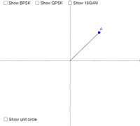
When looking at sinewaves as vectors in the plane, we associate a sinewave with the point whose Cartesian coordinates are (C,D).
A various timely video presentation of the above ideas, from about 4:50 to 9:50 in the video below. In particular, these two Geogebra files used in the video are great:


Cheers, Wayne

 
In the second, corrected round of simulations, the only reason for the difference in power per load is that the same set of 212V sources is connected delta vs wye. ...

My point still stands, given the limitations of the simulation (simulates an off-grid situation where the inverters are voltage sources). If the you change the voltage to the loads without changing the impedance of the loads, you're going to draw a different amount of power. And that's all the explanation you need for why the power drawn is different.
 
If we're posting Stand Up Maths this recent one is also topical. The presence of the the sqrt(3) in the simulations, along with the formula P=I^2R, happens to explain why we got twice the power with 2/3 the resistors and sqrt(3) times the voltage.

 
Both circuits are connected to the same Y transformer. The first file takes the output of the two inverters across and through the three resistors for a total of 89.7 watts with 300 peak (rather than 294). The second takes the output of the two inverters across and through the two resistors for a total of 179.6 watts with the same 300 volts. If I adjust voltage to 334 (peak of 240), the phase to phase inverters provide a total of 228 watts. But that introduces a slightly exaggerated power output; I wanted the exact same situation in both cases. The only difference should be the first is connected L-L and the second is L-N.
 
... The only difference should be the first is connected L-L and the second is L-N.

No. That will never prove anything. You need to study Ohm's Law. A resistor does not draw a fixed amount of power.

You could easily prove what we've been trying to tell you by simply adjusting the resistors in the simulations so that the ones that are energized in each simulation draw the same total amount of power. Then put watt meters on the inverters to show that the power matches. The inverters can deliver the power you desire to draw in both setups.
 
Both circuits are connected to the same Y transformer. The first file takes the output of the two inverters across and through the three resistors for a total of 89.7 watts with 300 peak (rather than 294). The second takes the output of the two inverters across and through the two resistors for a total of 179.6 watts with the same 300 volts. If I adjust voltage to 334 (peak of 240), the phase to phase inverters provide a total of 228 watts. But that introduces a slightly exaggerated power output; I wanted the exact same situation in both cases. The only difference should be the first is connected L-L and the second is L-N.
You are not comparing apples to apples in your two models.

You are you 212 Vrms power sources in both cases. With the two sources delta connected to the secondaries of your transformer, your secondary voltage is 212Y/122V. Each 1 kOhm load on the primary side of the 1:1 transformer is connected L-N and will dissipate V2/R = 1222/1000 = 15 W (average power; the peak power over a cycle will be twice that, or 30 W). You have 3 such loads (the open delta is able to fully power all 3 legs), for a combined average power of 45W.

With the two sources wye connected to the secondaries transformer, your secondary voltage is 367Y/212V. Except that with only two sources in this configuration, you are missing a leg of the 367Y/212V system. Each 1 kOhm load on the primary side of the 1:1 transformer is connected L-N and will dissipate V2/R = 2122/1000 = 45 W (average power; the peak power over a cycle will be twice that, or 90 W). You have only 2 powered loads in this configuration, for a combined average power of 90W.

With different voltages (212Y/122V vs 367/212V) and different numbers of loads (3 vs 2), you can't expect to get the same result.

Your models use independent voltage sources, so you are not modeling grid-tied inverters. If you had some grid tied inverters that could sync to any voltage (within bounds), and you connect them to a system where the secondary voltage is 208Y/120V (or 212Y/122V, but I suggest eliminating this discrepancy as it is just another possible source of confusion), then the delta connected inverters will sink to 208V, and the wye connected inverters will sink to 120V.

You can model this behavior perfectly well if you manually adjust your voltage sources in the wye connected case to be 1/sqrt(3) times the voltage in the delta connected case, i.e. 120V instead of 208V (or 122V instead of 212V if you insist on maintaining the discrepancy). If you do that, you will find the power dissipation per load to be identical between the two caes. To make the overall picture identical, either remove the 3rd load from the delta-connected case, or add the 3rd inverter to the wye connected case, so that you have an equal number of powered loads.

Cheers, Wayne
 
....

You could easily prove what we've been trying to tell you by simply adjusting the resistors in the simulations so that the ones that are energized in each simulation draw the same total amount of power. Then put watt meters on the inverters to show that the power matches. The inverters can deliver the power you desire to draw in both setups.

Alternatively, if you can simply put watt-meters on the inverters in both simulations, we would see that the power output is the same as the power consumption. That is, no energy is lost in one setup that isn't lost in the other, and the inverters are equally capable of powering the load in both scenarios, given how you've connected it.
 
I think this may be one of the greatest debate threads that I have ever seen on the Mike Holt forum. Could we ask input from the panel or even the man himself? Perhaps it's a good topic to explain in a future video, with the trend of more and more PV grid installs.
 
It is the same Y transformer, the same load resistors, and the same power sources. The only difference is L-L and L-N.
Yes, you've discovered that the same coordinated single phase power sources can give you different 3 phase voltages depending on whether you wire them wye or delta. (*)

And that the same load resistor will dissipate more power when you apply more voltage.

Since your initial concern was power transfer efficiency, follow jaggedben's last suggestion. In each of your two model, the sum of the power leaving the voltage sources will make the sum of the power going through the loads.

Cheers, Wayne

(*) But in a grid-tied system, you don't get a choice of what voltage to have your inverters put out. You must match them to the existing voltage system. Which means that whey you change from a wye connection to a delta connection, you must also change the inverter output voltage. Which you have failed to do in your model, so your model doesn't represent two different options for grid-tied inverters for a single existing voltage system.
 
It is the same Y transformer, the same load resistors, and the same power sources. The only difference is L-L and L-N.

A resistor isn't a load that draws a fixed amount of power. Study Ohm's Law. You are changing the voltage you supply to the loads when you change the inverters from L-N to L-L.
 
It is the same Y transformer, the same load resistors, and the same power sources. The only difference is L-L and L-N.
I already told you why that is. In a L-L connection the VA is split between the two conductors while in a L-N connection all the VA goes through a single conductor.
 
Apparently a 1/4 Ω resistor is sufficient to prevent the simulator from seeing a short circuit and allows all three power sources to be connected.

This is a little better circuit that should be wye with 944 W peak watts for a 30 Ω load:

https://tinyurl.com/22vfsmbr

And this should be exactly the same circuit connected delta with 2.8 kW peak for the same 30 Ω load:

https://tinyurl.com/22ed2v64

Forget the fact that traditionally we think wye and delta should be certain voltages. These are the same circuits, with the same transformer, with one connected in a wye configuration (944 W) and one connected delta (2.8 kW).

Why does this not accurately represent a wye-connected circuit transferring 30% of the delta-connected circuit?
 
It is interesting to note that the open delta source connected to the wye transformer configuration generates the full wye with all the correct L-L and L-N voltages.
OK, this was a side effect of the load impedances L-N being balanced. An open delta source creates all the L-L voltages, but with no other sources in the system (and therefore not a model of grid tied inverters), the neutral point of the wye secondary is completely floating.

Cheers, Wayne
 
OK, this was a side effect of the load impedances L-N being balanced. An open delta source creates all the L-L voltages, but with no other sources in the system (and therefore not a model of grid tied inverters), the neutral point of the wye secondary is completely floating.

Cheers, Wayne
I agree this does not fully represent the same as if it were tied to the grid. This output is most likely higher than if the inverters were looking at the L-L load equivalent and forming the output based on that and matching it back to the grid. Tied to the grid, it's worse.
 
Forget the fact that traditionally we think wye and delta should be certain voltages.
You can't. For a load of resistance R, the power dissipated is V2/R. So if you change the voltage the load sees, you change the power it dissipated.

These are the same circuits, with the same transformer, with one connected in a wye configuration (944 W) and one connected delta (2.8 kW).

Why does this not accurately represent a wye-connected circuit transferring 30% of the delta-connected circuit?
Because the voltage in the delta configuration is sqrt(3) times higher, and the square of sqrt(3) is 3 (V2/R), and so you dissipate 3 times as much power when you increase the voltage by a factor of sqrt(3).

Cheers, Wayne
 
Tied to the grid, it's worse.
No, tied to the grid, the L-L voltages would be the same in the two cases, as the voltages are fixed by the grid. Therefore the power dissipation on your primary loads would be the same.

For the fiftieth time, the grid-tied inverters are not independent voltage sources. They are dependent sources that match the voltage of the grid.

So if you are going to model grid-tied inverters with independent voltage sources, your model is inaccurate unless you manually ensure that the L-L voltages are the same in your two cases.

In other words, if you have a grid-tied inverter that could operate at either 120V or 208V, and you connect it to a 208Y/120V system, it will behave differently when connected to 120V (wye connected) versus when connected to 208V (delta connected). Your model does not reflect that difference in behavior. What your models so far have to say is not meaningful for grid tied inverters.

Cheers, Wayne
 
If we consider these two circuits as totally independent (not grid-connected), would it take (4) of the wye circuits, each with (3) 240 volt voltage sources, to come close to the same energy as the (1) delta with (3) 240 volt voltage sources?
 
Top