Single Phase/Two Phase Discussion

Status
Not open for further replies.
jpweygandt said:
This message is for David, Inspector Medina County Ohio, and all who have been on this discourse. I have learned a lot by reading here. I had an electrical contracting firm in Medina County at one time. 240 Volt 3 Phase Delta Corner Ground systems are not overly abundant in our area. At one time both voltages of Delta services were common. In Ohio most of them have been replaced with Y services. In the early days they were not grounded. The state required utilities to ground those services that were already installed and any new installations. New installations were usually meant to make existing systems larger or increases in amperage size.

Some existing ungrounded systems were corner grounded. The state required a grounded conductor for all services. Thus, the installations of Y services. I know of no services in Medina County, Ohio using Delta services. However, I know of at least several in Summit County, Ohio. Dry type transformers were used to create lighting services.

During World War I and II when copper was really scarce many three phase motors were fed with just two wires and the third was obtained at the location by attaching the third wire to the building steel. Thus the early Delta systems were less expensive and easier to install.

Jerry

Jerry,

You?re quite right about the lack of delta secondarys in Medina County. . My time spent as an inspector has been of no use in understanding or experiencing the configurations involved in this discussion. . I need to fall back on schooling and also years spent as a L38 wireman in Cuyahoga County and projects in Cuyahoga and Ashland Counties during my years as a contractor.

Since you have background with older corner grounded delta systems, I have a question for you.
?During World War I and II when copper was really scarce many three phase motors were fed with just two wires and the third was obtained at the location by attaching the third wire to the building steel. Thus the early Delta systems were less expensive and easier to install.?
The third grounded phase was delivering its current thru the building steel. . Now if the connection to the building steel would be lost on either the equipment end or the service end, I can imagine the danger to the worker if he was to touch that grounded phase while in contact with the building steel. . Up until the moment that the connection is lost, the worker could have touched the grounded phase wire without incident. . But then suddenly that same touch becomes lethal.

But as long as there is no lose of connection on the grounded phase, are you aware of any symptoms experienced by contact with the building steel or anywhere else along the grounded phase path ? . Since technically the workers body could be seen as a parallel path to ground, but obviously one of a much higher resistance, I can imagine a theoretically small amount of current taking the path thru the workers body resulting in a tingling or even a little shock possibly comparable to static discharge. . What was actually experienced by physical contact ?

David
 
I honestly think that if everyone would stop typing the word
"phase"
by itself without a qualifying word, the disputes would resolve and end.

If no one ever types the word "phase" but instead always types the words
"phase coil"
"phase load" or
"phase conductor"
I believe agreement could be found within a few posts.

David
 
Smart $ said:
But what constitutes a LINE?

Consider, just for the sake of discussion, a corner-grounded open-delta system, where the mutual corner is grounded. Do you or not have three LINE conductors? Do we not consider the grounded conductor as a LINE conductor just because it is grounded and common to both windings?

My description is not dependent upon the connection of a line (or even a neutral) conductor to ground. A corner grounded delta is still three phase.

If you try to call a 120/208Y neutral conductor a 3rd "line" then you will end up with unequal line-line voltages and the possibility that a 120/240 3-wire "Edison" circuit is really 3-phase and that 208Y/120 4-wire is 6-phase.

dnem
The presence or absence of a neutral point on the supply can not change the number of phases in a circuit. Just because the supply transformer is wye connected there is no requirement that the neutral point ever be referenced at all. This is similar to how a transformer with (2) 120V windings can be connected so that there is only a single 240V 2 wire output.

engy
The number of coils in a transformer can not be used to decribe the number of phases as evidenced by any 3-phase open delta arrangement.


My discussion (rant) has been an effort to promote the usage of the word "line" when discussing conductors (non-neutrals) and "phase" to mean the time relationship between line voltages.

Someday there may be a discussion on the word neutral (although it seems there is some NEC movement for the word "neutral" as refering to the conductor connected to a neutral point of a supply)
 
dnem said:
If you ground the center tap wire you get 2 sine wave values of identical voltage levels, but 180? apart. . It?s the result of looking from the center point of the coil in one direction for one value and then in the other direction for the other value.
Now if you ground one end of the coil, you?ll still get 2 sine wave values, but this time one with be double the voltage of the other one and both values with be in phase or 0? apart. . It?s the result of looking from one end of the coil to the center point for one value and then looking farther in the same direction to the farthest opposite end of the coil for the other higher voltage value.
And keep in mind that all of this is happening simultaneously.


winnie said:
If you have only _two_ conductors, as far as those two conductors are concerned, you have a single phase. Doesn't matter what you get these two conductors from; it is single phase. The question of single phase or more only becomes relevant if you have more than two conductors.
I agree.

If you have a 120/208Y system, and connect two perfectly balanced loads between the two lines, without a connection to the grounded conductor, then the loads will each see 104V. Now connect the mid point to the grounded conductor, and you get 120V on each load. The only thing that could change is phase angle.
Not only that, the neutral current will rise to that of the line current(s) in order to maintain the full 120v.


engy said:
I disagree. A 480-208Y120 has (basically) three 480-120V transformers (phases)

A 120/208 "single" phase feeder has two of the three 120V phases.
Still not two-phase or three-phase, just a portion of a 3-phase system where ya gan get 120 and 208V.
Yes, both at the same time, and (without comparing one to the other) each as a symmetrical sine wave. You can get 120v 1ph from either line to neutral, and 208 1ph from line to line, similarly to the 240/120 1ph system.

Where we really deviate from the behavior of the 240/120 1ph system is that the neutral current is not limited to the difference between the line currents. This is because of the non-180-deg. phase angle.

If you picture a balanced 208/120v system, let's say, with 10a on each line, there is zero neutral current. If you reduce the load on one phase to 5a, the neutral current rises by that same 5a; reduce it to zero, and the neutral current rises to 10a.
 
dnem said:
If you ignore the primary windings you would have a point. . But obviously you can?t ignore the primary windings. . Whether or not the 3rd phase coil is present, the voltages induced in the secondary coils hit maximum voltage value 120? apart. . 208/104 could only be achieved if they were 180? apart.

Thanks for answering that question David. I finally realized that last night (about midnight). I had to think through it. I'm not sure why it took me so long to realize it.
 
jim dungar said:
My description is not dependent upon the connection of a line (or even a neutral) conductor to ground. A corner grounded delta is still three phase.
Aye... but I said a corner-grounded OPEN delta, where the third phase is not served by a winding, but rather it is a compound phase derived from two other voltages w/out-of-phase freq's. The 208 voltage is also a compound phase, as it is not served directly by a winding.

jim dungar said:
If you try to call a 120/208Y neutral conductor a 3rd "line" then you will end up with unequal line-line voltages and the possibility that a 120/240 3-wire "Edison" circuit is really 3-phase and that 208Y/120 4-wire is 6-phase.
Yes, we end up with unequal line-line voltages. So. They are in fact unequal. Where is the problem here? [EDIT to add: I don't really want to call the grounded connection a LINE. I'd rather call it a {grounded} COMMON.]

There is no possibility a 120/240 1? 3W "Edison" circuit being 3-phase here. We cannot even have such a circuit on a 120/208Y service. At best the circuit would be 120/208 2? 3W circuit, wherein it supplies 120 volts twice over and 208 volts concurrently.

And 208Y/120 is six phase, as it has three served phases, and three compound phases. This goes back to one of your earlier statements:
jim dungar said:
Remember a single conductor is not a phase. A true phase is the voltage across two conductors.
The problem lies in the rationale that follows:
jim dungar said:
The standard convention is to refer to a Line-Line voltage as a phase voltage. This convention allows us to have consistency whether we are talking about wye or delta three phase connections and 2-wire or 3-wire single phase connections.
As I said earlier, rationale is often biased to the premise of the developing entity. Here we have the so-called convention—an attempt to bring consistency to various configurations—but it fails in this instance because its scope covers only the more commonplace configurations.
 
Last edited:
Smart $ said:
The problem lies in the rationale that follows:

jim dungar said:
The standard convention is to refer to a Line-Line voltage as a phase voltage. This convention allows us to have consistency whether we are talking about wye or delta three phase connections and 2-wire or 3-wire single phase connections.

As I said earlier, rationale is often biased to the premise of the developing entity. Here we have the so-called convention?an attempt to bring consistency to various configurations?but it fails in this instance because its scope covers only the more commonplace configurations.

Doesn't "standard convention" refer to line voltage as being the ungrounded voltage. . Line voltage is the same thing as line to line, isn't it ?

In the example of a corner grounded delta, the line to line would be ungrounded hot phase conductor to ungrounded hot phase conductor, while line to ground would be ungrounded hot phase conductor to grounded phase conductor. . So line to line would be the same as line to ground.

Whereas, in a wye line to line would be a higher voltage than line to ground.

I'm not sure if my understand of "line voltage" is technically correct or not.

David
 
Re: 'line to line' voltage.

I'm with dnem on this; when you get to the gritty details of these systems, you have to specify everything out. "line voltage" is a fine term to use when you are discussing a balanced system, but when you are discussing an intentionally unbalaced system it simply gets confusing. I work with 12, 17, and 18 phase VFD systems; 'line to line' voltage doesn't get you very far when there are 7 different possible combinations of phase angle difference :)

120/240 has 3 supply legs brought to the panel. Call the ungrounded supply legs A and A', and the grounded leg G.
The voltage between A and A' is 240V with phase angle 0.
The voltage between A and G is 120V with phase angle 0.
The voltage between A' and G is 120V with phase angle 180 ( or phase angle 0 with an inversion)
This system requires a panelboard with _2_ ungrounded bus bars, and a grounded bus.
With multi-wire branch circuits, current from the 2 ungrounded supply legs can balance on the shared grounded conductor.

From the point of view of the type of panel needed for this service, it is single phase.
From the point of view of the number of different line to line phase angles that this service can provide, it is single phase.
From the point of view of use of MWBCs and counting of current carrying conductors, it is single phase.
From the point of view of developing a rotating magnetic field, it is single phase.

120/208 has 3 supply legs brought to the panel. Call the ungrounded supply legs A and B, and the grounded leg G.
The voltage between A and B is 208V with phase angle 0.
The voltage between A and G is 120V with phase angle 30.
The voltage between B and G is 120V with phase angle 150
This system requires a panelboard with _2_ ungrounded bus bars, and a grounded bus.
With multi-wire branch circuits, current from the 2 ungrounded supply legs can never balance on the shared grounded conductor.

From the point of view of the type of panel needed for this service, it is single phase.
From the point of view of the number of different line to line phase angles that this service can provide, it is single phase.
From the point of view of use of MWBCs and counting of current carrying conductors, it is three phase with a phase missing.
From the point of view of developing a rotating magnetic field, it is a non-standard and unbalanced two phase, requiring the use of the two line-neutral phase angles.

120V corner grounded delta has 3 supply legs brought to the panel. Call the ungrounded supply legs A and B, and the grounded leg G.
The voltage between A and B is 120V with phase angle 0.
The voltage between A and G is 120V with phase angle 120.
The voltage between B and G is 120V with phase angle 240.
This system requires a panelboard with _2_ ungrounded bus bars, and a grounded bus.
With multi-wire branch circuits, current from the 2 ungrounded supply legs can never balance on the shared grounded conductor.

From the point of view of the type of panel needed for this service, it is single phase.
From the point of view of the number of different line to line phase angles that this service can provide, it is three phase.
From the point of view of use of MWBCs and counting of current carrying conductors, it cannot be used because the current on the grounded conductor could be as great as 1.732 * the current in the ungrounded conductors.
From the point of view of developing a rotating magnetic field, it is a balanced three phase supply.

(I just made this system up; I doubt that it is used anywhere :)

-Jon
 
Smart $

It makes no difference if the delta is open or if it is grounded. An open delta has the same voltages as a closed delta. A grounded reference oes not change the definition of it being a "line" or a neutral.

I have been trying to show how it can be easier to describe systems if the term "line conductor" is used instead of the term "phase conductor". This reserves the word "phase" to be to the time difference between line-line voltages. This definition is not dependent on if a neutral is available or not (like in a 2 wire circuit or in a 3-wire delta circuit).

If you are going to make statements like:
...208Y/120 is six phase, as it has three served phases, and three compound phases.
Then our discussion really needs to come to an end.

Edit:because I was slow in posting.
Jon,
From the point of view of developing a rotating magnetic field, it is a non-standard and unbalanced two phase, requiring the use of the two line-neutral phase angles.
Why does a 120/208Y circuit need to supply three conductors to a motor? Why not just 2 with 208V between them? Isn't 1 voltage between two conductors single phase?
 
Last edited:
jim dungar said:
Jon,

Why does a 120/208Y circuit need to supply three conductors to a motor? Why not just 2 with 208V between them? Isn't 1 voltage between two conductors single phase?

You can always supply a single phase load from a polyphase system.

120/240 can _only_ supply single phase loads.

120/208 is generally used to supply single phase loads. It can only supply a single phase _line to line_ load. It could in theory supply a two phase line to neutral load.

-Jon
 
jim dungar said:
Why does a 120/208Y circuit need to supply three conductors to a motor? Why not just 2 with 208V between them? Isn't 1 voltage between two conductors single phase?

Jim, AC motors need at least two phases for starting. In single phase motors this is done with extra windings and sometimes capacitors. Polyphase motors don't need this baggage and are therefore simpler to build for this reason. Of course, the two-phase system is now obsolete being supplanted by three-phase.
 
jim dungar said:
Smart $

It makes no difference if the delta is open or if it is grounded. An open delta has the same voltages as a closed delta. A grounded reference oes not change the definition of it being a "line" or a neutral.
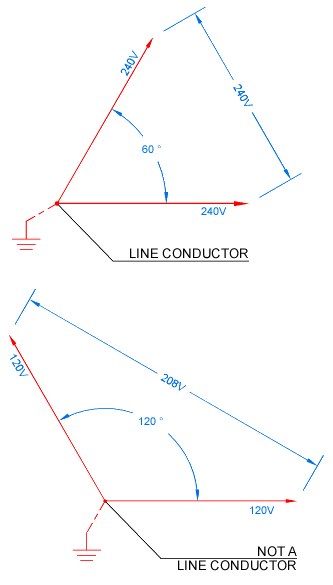
I believe you're missing the point. Please reference the following representative vector diagram. If you can't see the point I'm trying to make, you're correct in our discussion really needs to come to an end.

lineconductor.gif


jim dungar said:
I have been trying to show how it can be easier to describe systems if the term "line conductor" is used instead of the term "phase conductor".
I have no problem with this. I use try to use "line conductor" whenever the conductor is connected to a "line terminal". The problem I have is...
jim dungar said:
This reserves the word "phase" to be to the time difference between line-line voltages.
...as line-line voltages are not the only voltages having a time difference in a wye system.

jim dungar said:
This definition is not dependent on if a neutral is available or not (like in a 2 wire circuit or in a 3-wire delta circuit).
It is rather apparent it is dependent. By your definition, the Line to Neutral voltages in a wye have no consideration as phased.

jim dungar said:
If you are going to make statements like:
...208Y/120 is six phase, as it has three served phases, and three compound phases.
Then our discussion really needs to come to an end.
Hey, now! I made that statement based solely on the logic of one of yours?that being:
jim dungar said:
A true phase is the voltage across two conductors.
A [complete] wye system has four conductors, meaning it has six possible combinations of two conductors. Each of those six combinations have a different cycle timing using any one combination as a reference. Perhaps you had an omission and truly meant, "A true phase is the voltage across two LINE conductors." I don't know as I don't read minds.
 
Jon,

I like your approach of laying everything out line by line detailed and specific.
I have a question for you.

winnie said:
120V corner grounded delta has 3 supply legs brought to the panel.

From the point of view of use of MWBCs and counting of current carrying conductors, it cannot be used because the current on the grounded conductor could be as great as 1.732 * the current in the ungrounded conductors.

How can you get a higher current on the grounded leg ? . Where does the 1.732 figure come from ? . What would be going on in the delta that would cause an increase on just one leg ?

When you begin to explain it, I might end up reacting like Homer Simpson.
"D'oh !!"
But right now it's not making sense.

David
 
rattus said:
Jim, AC motors need at least two phases for starting. In single phase motors this is done with extra windings and sometimes capacitors. Polyphase motors don't need this baggage and are therefore simpler to build for this reason. Of course, the two-phase system is now obsolete being supplanted by three-phase.

This discussion has not been about motors but rather on the absolutely improper (according to the IEEE Red book and ANSI C84.1-1989) method of calling 120/208Y 3 wire circuits anything other than single phase.

Smart $
Connecting a conductor to ground does not change its basic identity as either a line, a neutral or a common.

I am not denying that there maybe "phases" associated with line-neutral voltages, only that they are not used to describe the circuit.

Any method used to define 1-phase, 2-phase, or 3-phase circuits can not require a line to neutral voltage, because there are variations of each supply that do not have a neutral connection point. There is no reference book that I have been able to find that ever describes the number of phases in a circuit based on a line-neutral voltage.

Take any 2 wire load supplied by two windings of a transformer, either two windings in series like 120/240V or in open wye like 120/208Y. Because this is a two wire circuit there can only be a single current loop. This single current creates a single voltage drop across the load - therefore this must be a single phase circuit. Now add a second load that is connected across only one of the two windings used in the previous circuit. How can the addition of this load affect the number of phases in the circuit? (And yes, I am ignoring an open-delta arrangement.)
 
dnem said:
How can you get a higher current on the grounded leg ? . Where does the 1.732 figure come from ? . What would be going on in the delta that would cause an increase on just one leg ?

Just to be clear, I was describing a strange beast: a corner grounded delta, but at only 120V, serving single phase loads. That is why I noted that such an installation is not actually used anywhere.

When multiple circuits share a conductor, the current on that conductor is the vector sum of the current in the individual circuit currents. Just to make things easier, one generally presumes that both circuits are carrying their _maximum_ current, and finds the current on the shared conductor in that case, but of course in reality this is just a worst case scenario.

In a 120/240V single phase system, current flowing from leg A is generally 180 degrees out of phase from current flowing from leg B. The shared conductor current tends to balance out, and in the worst case of two matched circuits fully loaded, the net current on the shared conductor is 0.

In a 120/208V 'single phase derived from a 208Y/120V three phase' system, current flowing from leg A is generally 120 degrees out of phase from current flowing from leg B. The vector sum of these two circuits tends to balance somewhat, and in the worst case of two matched circuits fully loaded, the net current on the shared conductor is equal to the current on the ungrounded legs.

As the phase angle difference gets smaller, the current flow is more and more in phase, and less current balance occurs. In the example that I created, a 120V corner grounded delta, current flowing between leg A and the grounded conductor is generally 60 degrees out of phase with current flowing between leg B and the grounded conductor. The vector sum of X amp flowing at 0 degrees and X amps flowing at 60 degrees is 1.732 * X amps flowing at 30 degrees.

-Jon
 
jim dungar said:
This discussion has not been about motors but rather on the absolutely improper (according to the IEEE Red book and ANSI C84.1-1989) method of calling 120/208Y 3 wire circuits anything other than single phase.
[/ QUOTE]

Jim, I think you are right about the description. Although there are three phase angles involved here, they can only supply single phase loads. Now one could drive a 2-phase motor which would probably run but not very well, so that doesn't count.

However, if 120V loads are driven, you must agree that a common return (not a neutral) is required. Right?
 
winnie said:
As the phase angle difference gets smaller, the current flow is more and more in phase, and less current balance occurs. In the example that I created, a 120V corner grounded delta, current flowing between leg A and the grounded conductor is generally 60 degrees out of phase with current flowing between leg B and the grounded conductor. The vector sum of X amp flowing at 0 degrees and X amps flowing at 60 degrees is 1.732 * X amps flowing at 30 degrees.
If it helps, picture carrying the collapsing phase-angle difference to the extreme, where the two ungrounded conductors are in phase: the neutral current is the sum of those of the two ungrounded conductors.

An example of this is the grossly-overloaded shared neutral when someone mistakenly connects the two ungrounded conductors to the same phase on a multi-wire circuit: the currents add instead of cancelling.
 
jim dungar said:
Smart $
Connecting a conductor to ground does not change its basic identity as either a line, a neutral or a common.
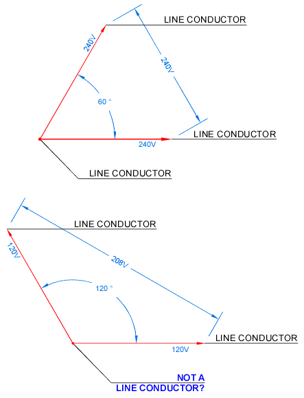
For some reason you are stuck on the grounded connection as having bearing on my point. It does not. I only used a corner-grounded, open-delta system because of it's configuration similarity to 120/208Y service. Forget about the grounded connection...

lineconductor2.gif


You have already stated:
jim dungar said:
If you try to call a 120/208Y neutral conductor a 3rd "line" then you will end up with unequal line-line voltages and the possibility that a 120/240 3-wire "Edison" circuit is really 3-phase and that 208Y/120 4-wire is 6-phase.
But we're not dealing with a neutral conductor on a 120/208 service. The grounded conductor is no more than that with respect to this service. This is in effect the entire point. It is not a neutral with respect to the service so therefore it is a line conductor. Doesn't matter if the voltages are unequal. What matters is the fact the sum of the lesser voltages do not add up to the greater voltage, making it, in absolute truth and defying convention, not a single phase service.

jim dungar said:
I am not denying that there maybe "phases" associated with line-neutral voltages, only that they are not used to describe the circuit.

Any method used to define 1-phase, 2-phase, or 3-phase circuits can not require a line to neutral voltage, because there are variations of each supply that do not have a neutral connection point.
I'm well aware of this... such as a delta 3-wire supply. However there is a vectorial "neutral voltage point" or a "virtual neutral", where all system voltages can be represented as vectors from this point. In a balanced voltage polyphase system, the outbound ends of the vectors all lie on the same circle, which has its center at the neutral voltage point. Even single phase systems can fit this "yet to be adopted" convention.

jim dungar said:
Take any 2 wire load supplied by two windings of a transformer, either two windings in series like 120/240V or in open wye like 120/208Y. Because this is a two wire circuit there can only be a single current loop. This single current creates a single voltage drop across the load - therefore this must be a single phase circuit. Now add a second load that is connected across only one of the two windings used in the previous circuit. How can the addition of this load affect the number of phases in the circuit? (And yes, I am ignoring an open-delta arrangement.)
Again you are staging the question, but I'll answer out of courtesy...

It can't (ignoring an open delta arrangement :) ).

However, we've already established there can only be one phase across a two-wire load! It doesn't matter how many you have or which winding(s) they are connected to... so let's move on.

My turn to ask a question...

On a 120/208Y service we have two equal single phase loads connected to a MWBC. Is there current through the grounded conductor?

If the answer is yes the service, from a strict physics point of view, is not a single phase service.

In a nutshell, I could care less what it is called, because I'm quite familiar with wye systems and the pertinent considerations... and it's far from the first instance I've run across a misnomered description. What concerns me is the electricians, perhaps inspectors that are not aware of the considerations... and I see a prohibited neutral reduction getting overlooked somewhere [ref: 220.61(C)(1)]!!!
 
Last edited:
Smart $ said:
My turn to ask a question...

On a 120/208Y service we have two equal single phase loads connected to a MWBC. Is there current through the grounded conductor?

If the answer is yes the service, from a strict physics point of view, is not a single phase service.

In a 120/208Y MWBC it is possible for the conductor connected to the neutral point to carry a current equal to one of the line conductors. This conductor is carrying the unbalance between the line conductors which is the same function as the neutral conductor in a 120/240 3-wire circuit. This conductor must be counted as a current carrying conductor.

This does not prevent it from being a single phase circuit. If a 2-wire line-line load connected to an open wye transformer is a single phase circuit then simply adding a conductor to the neutral point does not change the number of phases. ANSI and IEEE both define phases based on line-line voltages not line-neutral voltage, nor line to line currents, nor line to neutral currents, nor the number of windings in a transformer bank even though these items usually have the word "phase" associated with them.
 
Last edited:
Smart $ said:
My turn to ask a question...

On a 120/208Y service we have two equal single phase loads connected to a MWBC. Is there current through the grounded conductor?

If the answer is yes the service, from a strict physics point of view, is not a single phase service.
The answer is indeed yes, but the service itself is not a single-phase service whether the neutral is used in a given circuit or not. It's the circuit that may or may not be single-phase, depending on whether there is any line-to-neutral load.

A line-to-line load is single phase, as is the 2-wire circuit supplying it. A pair of line-to-neutral loads are each single phase. The multi-wire circuit supplying them is poly-phase, because there is a difference in timing between the two voltage peaks, relative to the reference point (the neutral).

If you supply both line-to-line and line-to-neutral loads from a 2-line-plus-neutral 3-wire circuit, the load determines which portion is 1-phase and which is poly-phase. The load current portions is what really matters. Only the line-to-neutral loads will exhibit neutral current.

There will be both 1-phase and poly-phase current components, with different peak timings, super-imposed on the conductors (ungrounded as well as grounded), all at the same time. (I'm talking resistive loads here, by the way; reactances are another matter.)
 
Status
Not open for further replies.
Top