Are there differences in the flow of electrons in a single plase 230V circuit to a 208V 3-phase circuit uses only two of the 3 phases?
1. Take the single phase 115V part of the 230V circuit. (Does the current flow at a different time then the other 115v part of the 230V circuit?)
2. What is the path that the electrons flow on for the 115V part of the 230V circuit [since there is no return path for each leg of the 230V circuit, no neutral/grounded path]?
3. Whats the difference in a 208V circuit between two phases for 208V feeding a load. There does seem to be a time difference between phases.
4. In both of the above cases do the electrons flow back to the source or what happens to them.
5. Can you provide a reference source to back up your conclusions, if so what are they?
1. no difference
2. The sum of the voltages around any closed loop = zero (Kirchoff's law). 115v source through 115v load through the neutral, or if no neutral, 230v source through two 115v loads in series.
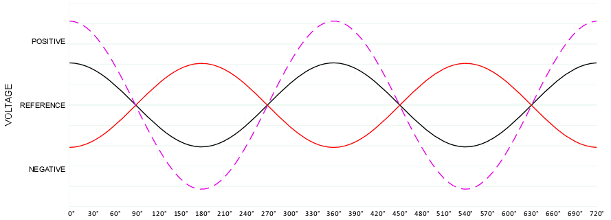
3. Three phase originates in and is ideally suited for rotating machinery, motors and generators. In a two pole rotating machine, the armature is a North to South constant bar magnet and it sweeps past the A, B, C field coil pairs, generating a sinewave voltage in the field coils. The A, B, C field coils are physically seperated by place and so also seperated by time, as the rotating armature magnetic field induces voltage sequentially, in the A field coil, then the B field coil, then C, then A again.
Connecting a load to A and C in series at 115v source volts each, if A and C were matching sinewaves in time, the voltage would add in series to 230v (0 degree phase difference). Since A and C sinewaves are generated at different times, for part of the cycle C is negative when A is positive and the sum sometimes is a subtraction of voltage rather than addition. The sum of two sinewaves is another sinewave, but at 208v rms because of the part of the cycle where the voltages subtract rather than add. If A and C were seperated by 180 deg, the sum in series would be 0 volts.
4. Voltage travels from source to load around the circuit. The individual electron mass barely moves. You can walk faster than the electron moves.
"Numerical example
Electricity is most commonly conducted in a copper wire.
Copper has a density of 8.94 g/cm?, and an
atomic weight of 63.546 g/mol, so there are 140685.5 mol/m?. In 1
mole of any element there are 6.02?1023 atoms (
Avogadro's constant). Therefore in 1m? of copper there are about 8.5?1028 atoms (6.02?1023 ? 140685.5 mol/m?). Copper has one free electron per atom, so
n is equal to 8.5?1028 electrons per m?.
Assume a current
I=3 amperes, and a wire of 1 mm diameter (radius in meters = 0.0005m). This wire has a cross sectional area of 7.85?10-7 m2 (
A= π?0.00052). The charge of 1
electron is
q=1.6?10−19 Coulombs. The drift velocity therefore can be calculated:
Analysed dimensionally:
[V] = [Amps] / [electron/m3] ? [m2] ? [Coulombs/electron]
= [coulombs] / [seconds] ? [electron/m3] ? [m2] ? [Coulombs/electron]= [meters] / [second]Therefore in this wire the electrons are flowing at the rate of 0.00029 m/s, or very nearly 1.0 m/hour"
http://en.wikipedia.org/wiki/Drift_velocity
The question you're asking, to understand it and to work it, the essential information is the transformer turns ratio, V primary /V secondary = turns primary / turns secondary, and the kVA rating.
In the single phase example of one iron core, one primary winding, and two secondary windings. The primary is energized and current flow induces a dense magnetic field in the iron core. A changing magnetic field is necessary to induce voltage in the secondary winding (Faraday or Lenz). Run DC through the primary and secondary voltage is zero, no matter what else.
There is a right hand rule for current flow through coils or turns of wire and magnetic field direction. The iron core's magnetic field is changing direction at the same frequency as the sinewave voltage driving the primary current.
On the secondary side, it can be simple. Every coil or turn of wire occupies the same place and the same time, so every turn of wire sees the same magnetic core field and same induced voltage, in synch. Turns connected in series, the voltages add. Turns connected in series but wound in the opposite diirection, CCW adding to CW turns, the voltages subtract. Add the turns matching polarity in parallel and the current rating adds. Add turns in parallel but opposite polarity (opposite winding direction) and the secondary is shorted.
Single phase, two secondary 115v windings. Added in series wound in the same direction, the turns ratio from primary to secondary changes by a factor of 2 and the voltage doubles.
Single phase, two secondary 115v windings. Added in series wound in opposite directions and you have a secondary with zero turns and zero volts. +X turns + -X turns = zero turns. This is how an auotransformer secondary at 24 volts can either add 24 v or subtract 24 v depending on reversing two wires.
Single phase, two secondary 115v windings. Added in parallel wound in the same direction, the turns ratio stays the same, voltage is same, and the current rating doubles. There is zero voltage difference between each winding with matching sinewaves, so no short through the other winding. Add in parallel, wound in opposite directions and one winding voltage peaks when the other is low and the reverse. The sum of the voltages is 2x the winding voltage and short circuit current flows because the winding is a low impedance path with a voltage difference imposed on it.


