single vs. 3 phase

Status
Not open for further replies.
hardworkingstiff said:
If I understand this question, you are talking about line to line load (no neutral connection) of a 120/208 'single-phase' circuit.

Delta/Wye would have current on all 3 primary conductors and 2 secondary conductors, but current would only be flowing through 2 primary coils and 2 secondary coils.

Wye/Wye would have current on 2 primary conductors (and the neutral of the primary, but not the 3rd phase conductor) and 2 secondary conductors (with no current on the neutral of the secondary), current on 2 primary coils and 2 secondary coils.

Right/Wrong?

Mostly right, but let's see what others have to say, especially about the relative magnitudes of the currents in the delta-wye case.
 
rattus said:
Alright. Now what are the primary currents for a line to line load?
For the secondary: two windings and two line conductors with 1x current. no current in third winding or neutral.

For the delta-wye primary:
two windings and two line conductors with 1x current. one line conductor with 2x current. one winding with no current.

For the wye-wye primary:
two windings and two line conductors with 1x current. no current in third winding or neutral.

[edit: I'm not counting the common between two transformers as a neutral]
 
Last edited:
hardworkingstiff said:
If I understand this question, you are talking about line to line load (no neutral connection) of a 120/208 'single-phase' circuit.

Delta/Wye would have current on all 3 primary conductors and 2 secondary conductors, but current would only be flowing through 2 primary coils and 2 secondary coils.

Wye/Wye would have current on 2 primary conductors (and the neutral of the primary, but not the 3rd phase conductor) and 2 secondary conductors (with no current on the neutral of the secondary), current on 2 primary coils and 2 secondary coils.

Right/Wrong?
right, except that the wye-wye would have no primary neutral current
 
The details (unless I type it wrong):
For Delta-Wye L-N load on A & B winding
Secondary Conductor: A= 1x, B=1x, C=0, N=1x
Secondary Winding: A= 1x, B=1x, C=0
Primary Conductor: A= 1x, B=1.732x, C=1x
Primary Winding: A= 1x, B=1x, C=0

For Wye-Wye L-N load on A & B winding
Secondary Conductor: A= 1x, B=1x, C=0, N=1x
Secondary Winding: A= 1x, B=1x, C=0
Primary Conductor: A= 1x, B=1x, C=0, N=1x
Primary Winding: A= 1x, B=1x, C=0

For Delta-Wye L-L load on A & B winding
Secondary Conductor: A= 1x, B=1x, C=0, N=0
Secondary Winding: A= 1x, B=1x, C=0
Primary Conductor: A= 1x, B=2x, C=1x
Primary Winding: A= 1x, B=1x, C=0

For Wye-Wye L-L load on A & B winding
Secondary Conductor: A= 1x, B=1x, C=0, N=0
Secondary Winding: A= 1x, B=1x, C=0
Primary Conductor: A= 1x, B=1x, C=0, N=0
Primary Winding: A= 1x, B=1x, C=0, N=0
 
http://en.wikipedia.org/wiki/Polyphase_system

http://en.wikipedia.org/wiki/Polyphase_system

"A two-phase supply with 90 degrees between phases can be derived from a three-phase system using a Scott-connected transformer. . .A 3-wire system with two phase conductors 180 degrees apart is still only single phase. Such systems are sometimes described as split phase."

A residence has two voltage sources, the first at 120v at an angle of zero degrees, the second at 120 v at an angle of zero or 180 degrees. No matter how you strap each winding (but no paralleling) or how the second source is phased, you can only get 120, 240 or zero volts.

If one of these same voltage sources is at some angle other than 0 or 180, you now have a two-phase system. No wiring change, you just shift the phase angle.
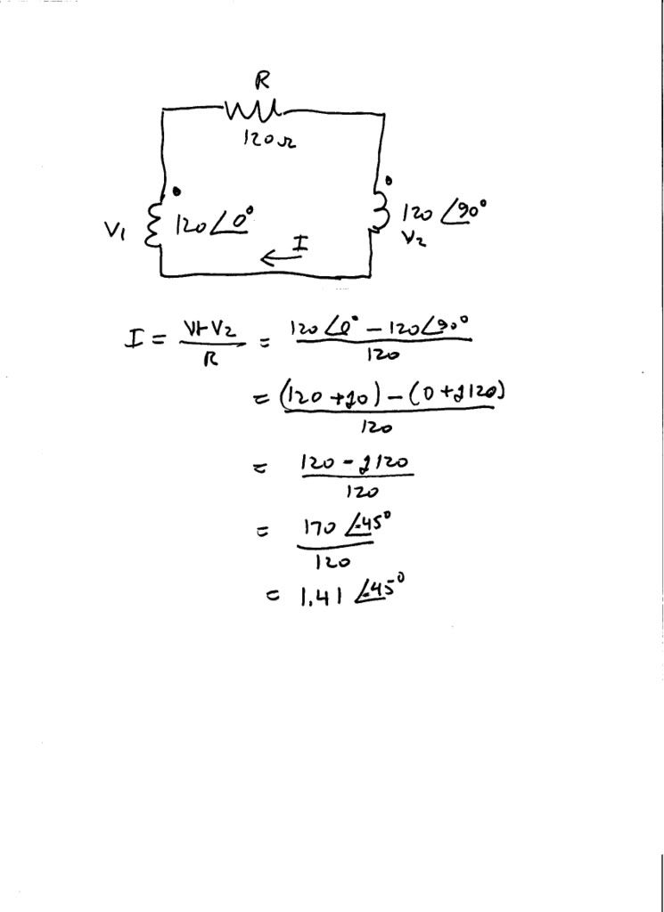
If you have a resistor in series with these two sources in series, you can get any current from zero up to 2xV/R by just shifting the phase angle.
 
hardworkingstiff said:
I'm confused.

Originally Posted by mivey
right, except that the wye-wye would have no primary neutral current.

The exact same current flows through the primaries, therefore there is no unbalanced current to flow in the primary neutral.

Originally Posted by mivey
For Wye-Wye L-N load on A & B winding
Secondary Conductor: A= 1x, B=1x, C=0, N=1x
Secondary Winding: A= 1x, B=1x, C=0
Primary Conductor: A= 1x, B=1x, C=0, N=1x
Primary Winding: A= 1x, B=1x, C=0

Kirchoff's current law:

Ia + Ib + Ic + In = 0 (phasorially)

If we have a balanced load, then In = 0.

If we make Ic = 0, that current is shifted to In.

True for primary and secondary.
 
hardworkingstiff said:
I'm confused.
In your post, the top quote is for line to line (L-L) loads and the bottom is for line to neutral (L-N) loads.

edit to add:
rattus said:
...If we have a balanced load, then In = 0...
As rattus pointed out, we need a balanced load for the L-N case. The load was not balanced so we wound up with neutral current.
Example, for current "X": In = Ia+Ib+Ic = X<0 + X<-120 + 0 = X<-60 = current into the common terminal from the neutral.

For the L-L case, Ia = -Ib so there was no neutral current (Ic=0).
 
Last edited:
Lxnxjxhx said:
"A two-phase supply with 90 degrees between phases can be derived from a three-phase system using a Scott-connected transformer. . .A 3-wire system with two phase conductors 180 degrees apart is still only single phase. Such systems are sometimes described as split phase."

A residence has two voltage sources, the first at 120v at an angle of zero degrees, the second at 120 v at an angle of zero or 180 degrees. No matter how you strap each winding (but no paralleling) or how the second source is phased, you can only get 120, 240 or zero volts.

If one of these same voltage sources is at some angle other than 0 or 180, you now have a two-phase system. No wiring change, you just shift the phase angle.
If you have a resistor in series with these two sources in series, you can get any current from zero up to 2xV/R by just shifting the phase angle.
You can't shift the phase angle without a 3rd reference point that does not fall along the axis between the two voltage points. If you put one resistor between two steady-state sinusoidal sources of the same frequency you will only have one voltage waveform across the resistor and it will be a net single phase voltage across the resistor. Comparing the voltage from one end of the resistor to the midpoint of the resistor with the voltage from the other end of the resistor to the midpoint of the resistor will show that the two ends display a 180 degree difference.

The 90 degree "two-phase" system does not meet the criteria for a two-phase system by polyphase definitions. It was called two-phase by convention, much like the names we use today are by convention and can't necessarily stand up to the strictest of definitions.
 
I'm not sure what you mean. Here's what I mean. . .
twophase003.jpg
 
mivey said:
The 90 degree "two-phase" system does not meet the criteria for a two-phase system by polyphase definitions. It was called two-phase by convention, much like the names we use today are by convention and can't necessarily stand up to the strictest of definitions.

Say what???

Please cite a reference.
 
mivey said:
For Delta-Wye L-L load on A & B winding
Secondary Conductor: A= 1x, B=1x, C=0, N=0
Secondary Winding: A= 1x, B=1x, C=0
Primary Conductor: A= 1x, B=2x, C=1x
Primary Winding: A= 1x, B=1x, C=0
Are you certain about that?

Consider the following diagram in your evaluation...

primaryandsecondarycurrents.gif
 
Lxnxjxhx said:
...I'm not sure what you mean...
Write out the function of V1-V2 using cosine and you should see what I mean. jim dungar has several posts explaining his view of two line conductors constituting a single phase.
jim dungar said:
...Please cite a reference...
I believe I have earlier but with over 400 posts, it may have been missed. I'll see if I can find it.[edit: see #367]
Smart $ said:
...Are you certain about that...
Yes (as long as my chicken scratch is readable enough). Don't forget that we are not talking about a balanced three phase load. The two load scenarios being discussed were two L-N loads or one L-L load. Also, not that it matters much for this discussion, but your phasors are drawn in reverse rotation.
 
Last edited:
mivey said:
Yes (as long as my chicken scratch is readable enough). Don't forget that we are not talking about a balanced three phase load. The two load scenarios being discussed were two L-N loads or one L-L load.
Yes, I realize this, and I am referring only to the one L-L secondary load. The current of such a single load maintains the same phase angle all the way to the source, does it not? In this case, you have to keep in mind, the load current is exactly 180? out of phase with B-phase supply voltage.

I am not saying you are wrong, because I am not certain myself as to what is right. ;) But if you are right, teach me why. :grin:

Also, not that it matters much for this discussion, but your phasors are drawn in reverse rotation.
Sorry, but they are not. I'm using positive phase angle notation in the diagram. If I were to use negative or true phase angles of -120? and -240?, the diagrams would flop about the 0? reference axis. The phasors would then be reversed and the rotation would be counter-clockwise.
 
Smart $ said:
But if you are right, teach me why.
OK. Let's see if this makes sense:

Draw three secondary coils oriented in a vertical stack. Let the top coil be A, the middle coil be B, and the bottom coil be C. Connect the bottoms of the coils together and bring a line out and call it N. The tops of the coils will be the A, B, & C line conductors. Bring a line out from A, through a resistor and back to B.

The current x<0 leaves A and goes through the resistor, and enters the top of the B coil (Ia = -Ib). This current goes down through the B coil and exits at the common connection. We know x<0 must enter the bottom of the A coil since it also leaves the top of the A coil. There is no remaining current left to run in the neutral so it has 0 current. C has zero current because it is open.

Now for the delta primary side (a,b,c with 1:1 ratio and no phase shift). Line up the primary coils next to the secondary coils and connect them with the bottom of a to the top of b, the bottom of b to the top of c, and the bottom of c back to the top of a. Let the line conductor a, b, c come in at the top of the respective coils.

Use the polarity such that coil a has x<0 entering the top because coil A has x<0 leaving the top. Coil b has x<0 leaving because coil B has x<0 entering. Line conductor b current (into the coils) = current entering bottom of coil a (-x<0) plus the current entering the top of coil b (-x<0) = 2x<180. x<0 enters the bottom of coil b and since coil c has no current, the line conductor c has x<0 coming into the coils. Also, since the coil c has no current, the line a conductor current is the same as the current entering coil a or x<0.

After all of this text, a picture may have been easier. Let me know if you did not follow that.

Smart $ said:
...Sorry, but they are not. I'm using positive phase angle notation in the diagram. If I were to use negative or true phase angles of -120? and -240?, the diagrams would flop about the 0? reference axis. The phasors would then be reversed and the rotation would be counter-clockwise.
For a-b-c rotation, the a phasor would be drawn at 0 degrees, the b phasor at -120 (or 240) degrees, and the c phasor at 120 (or -240) degrees.
[edit: Try this handy toy: http://www.powerstandards.com/PQTeachingToyIndex.htm ]
 
Last edited:
mivey said:
...After all of this text, a picture may have been easier. Let me know if you did not follow that.
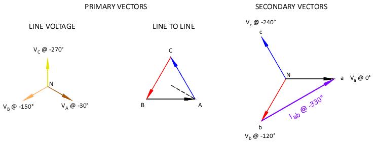
Oh, I followed it alright... The problem is that it is incorrect, namely your current angles. A purely resistive load across Lines a and b of a wye secondary has a current 30? out-of-phase with the windings voltage: +30? to a<0? voltage and -30? to b<-120? voltage (using "true" phase angles, φ). Additionally, a dela-wye transformer has a 30? phase shift between primary and secondary Line voltages: if a<0? then A<-30?, B<-150?, and C<-270?. Therefore Iab's phase angle is -330? and primary Line B voltage is -150?, exactly 180? out-of phase.

For a-b-c rotation, the a phasor would be drawn at 0 degrees, the b phasor at -120 (or 240) degrees, and the c phasor at 120 (or -240) degrees.
"a-b-c rotation" is counter-clockwise. The following image uses negative or true phase angles (φ) but is referenced to secondary a voltage.

primaryandsecondarycurrents-2.gif


I'm just not seeing IA = 1x, IB = 2x, and IC = 1x. I would be more apt to believe IB = 1.732x
 
Smart $ said:
Oh, I followed it alright... The problem is that it is incorrect, namely your current angles. A purely resistive load across Lines a and b of a wye secondary has a current 30? out-of-phase with the windings voltage: +30? to a<0? voltage and -30? to b<-120? voltage (using "true" phase angles, φ). Additionally, a dela-wye transformer has a 30? phase shift between primary and secondary Line voltages: if a<0? then A<-30?, B<-150?, and C<-270?. Therefore Iab's phase angle is -330? and primary Line B voltage is -150?, exactly 180? out-of phase.


"a-b-c rotation" is counter-clockwise. The following image uses negative or true phase angles (φ) but is referenced to secondary a voltage.

primaryandsecondarycurrents-2.gif


I'm just not seeing IA = 1x, IB = 2x, and IC = 1x. I would be more apt to believe IB = 1.732x
If we let Van=120<0, Vbn=120<-120, Vcn=120<120 then the current through a resistor connected from a to b is (Van-Vbn)/R = 207.85<30 / R. The ANSI/IEEE standard is that the high voltage leads the low voltage by 30 degrees for delta-wye or wye-delta banks. In the field, it may not always be the case. But that was not the point of the illustration. Pick whatever current angle you want (I picked zero for simplicity's sake), and work through the problem and see what you get. I'll check my chicken scratch again but do not have the time right now.

I'm not sure what you are doing with the rotation. I'll read through it again later but it must be the terminology you are using that is throwing me off.

[edit: clarity]
 
Last edited:
Status
Not open for further replies.
Top