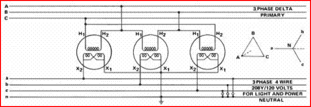
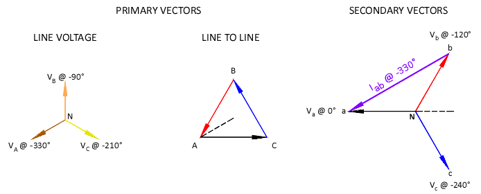
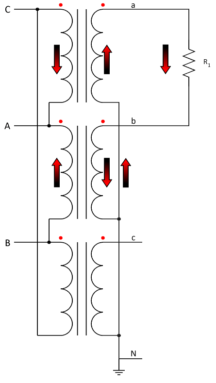
My earlier diagrams have the low voltage leading the high. To have high lead low, the primary coils must be connected reverse polarity from your earlier description (i.e. connected CA?an, AB?bn, and BC?cn).mivey said:If we let Van=120<0, Vbn=120<-120, Vcn=120<120 then the current through a resistor connected from a to b is (Van-Vbn)/R = 207.85<30 / R. The ANSI/IEEE standard is that the high voltage leads the low voltage by 30 degrees for delta-wye or wye-delta banks. In the field, it may not always be the case. But that was not the point of the illustration. Pick whatever current angle you want (I picked zero for simplicity's sake), and work through the problem and see what you get. I'll check my chicken scratch again but do not have the time right now.
I'm not sure what you are doing with the rotation. I'll read through it again later but it must be the terminology you are using that is throwing me off.

However, this does not change the basic premise of anything I have wrote. I have redrawn my diagram to match the standard delta-wye bank configuration and symbology above.

Now, when you talk current vectors primary versus secondary, you have to reverse polarity. So where I note Iab@-330 on the secondary, it transfers to the primary with a phase angle of -150?... the exact opposite angle of what I said earlier... but the common node is no longer Line B, but Line A@-330?, also the exact opposite angle of what I said earlier.
By conforming to this hi lead lo voltage standard has definitely made your numbers wrong. But the question of 'what is right?' still remains...!!!


