single vs. 3 phase

Status
Not open for further replies.
crossman said:
Okay Don, let's go with your example of L1 and L2 being opposite polarities, and assume that we both realize that there must be two points to measure voltages.

If L1 and L2 are opposite polarity, that means that if one of them is positive, the other one is negative. This infers that when one of them is at a positive peak, the other is at a negative peak. Now, if we graph the 2 sine waves based on the condition of L1 at positive peak while L2 is simultaneously at negative peak, then we will see 2 sine waves which are 180 degrees out of phase.
Crossman, actually you would have only one sine wave representing the difference of potential, (voltage), between L1 and L2. If the peak voltage is 120 then at 90? into the first cycle you would measure 120 volts at that time between L1 and L2. If L1 were positive, then L2 would be negative if L1 were negative, then L2 would be positive. The sine wave doesn't represent L1 or L2, it represents the voltage between them. Don
 

rattus

Senior Member
No error, no joke:

No error, no joke:

Don Randall said:
Rattus, Is this an error, or did you really mean it? If you do mean it, why not explain how you come to that conclusion? Don

If V1 and V2 are inverses, their difference is,

v12 = Vp*[sin(wt) -(-sin(wt))] = 2Vp*sin(wt)

V1 and V2 are out of phase by 180 degrees as well.

If they are in phase, they are identical, therefore their difference is zer9.

V12 = Vp[sin(wt) - sin(wt)] = 0

"In phase" means that the positive peaks, negative peaks, pos zero crossings, and negative zero crossings occur at the same times.
 
rattus said:
"In phase" means that the positive peaks, negative peaks, pos zero crossings, and negative zero crossings occur at the same times.
I would think that with a single sine wave that is precisely what is happening. That is, the sine wave for L1 L2. Don
 

rattus

Senior Member
Subscripts:

Subscripts:

First: Scope of the argument

The argument at the moment is whether or not L1 and L2 are out of phase. This boils down to the meaning of the symbols and subscripts. Personal preferences are not pertinent..

Second: Proper terminology

It is improper to speak of the ?phase angles? of L1 and L2 because they are not phasors; they are circuit nodes?wires if you will. We should speak of the phase angles of the voltages, V1 and V2.

Third: Subscripts

The convention is that the first subscript of the voltage symbol denotes the location of the ?hot? probe and the second denotes the location of the reference probe. That being the case, to view V1 and V2, the scope probes should be on L1 and L2 which leaves N for the ground clips. So, we are really observing V1n and V2n whether the second subscript is written or not. Placing a probe on N and clipping the ground to L2 does not measure the voltage on L2. It measures its inverse. Plus, the ground clips on many scopes are tied to the EGC?so watch it!
 

mivey

Senior Member
rattus said:
..."In phase" means that the positive peaks, negative peaks, pos zero crossings, and negative zero crossings occur at the same times.
Don, we have discussed the multiple uses of the term "phase" before. When talking about a phase-shift, the audio guys are talking about a time-shift. But "phase" is also used as rattus described, and is not a time shift.
 

mivey

Senior Member
Don Randall said:
I would think that with a single sine wave that is precisely what is happening. That is, the sine wave for L1 L2. Don
True, but you have zero amplitude if the signals at L1 and L2 are identical.
 

rattus

Senior Member
Don Randall said:
I would think that with a single sine wave that is precisely what is happening. That is, the sine wave for L1 L2. Don

"In phase" has no meaning for a single waveform. We are discussing the phase difference between V1 and V2.
 

mivey

Senior Member
rattus said:
"In phase" has no meaning for a single waveform. We are discussing the phase difference between V1 and V2.
Based on #661, I thought that was what he meant.
 

mivey

Senior Member
coulter said:
No, switch is shown open:D

carl
Pay attention! There are some who say you don't need a closed loop for current to flow. These are Evel Knievel electrons that can jump the switch. :D

[edit: based on another thread]
 

coulter

Senior Member
Don Randall said:
Carl, Above is a previous post you could comment on also, if you like. I was a little sparse on details in the post with the drawing, ...
Nope, no comments - you got it. Your post 661 is a clear example.

Don Randall said:
... I'm a little surprised that you don't think there are opposing polarities. ...
Yeah, I didn't phrase that very well

Don Randall said:
...Unless, I'm mistaken, (you will correct me if I am), every point in the circuit would be in phase with every other point, with respect to the timing and direction of the pulses. ...
I won't correct you, I'll say I don't get it. Anytime I'm looking at phase angle, it is a voltage drop across an impedance or a source, and compared to some reference source (reference source usually <0) (where < = phase angle, cause I can't make a phase angle symbol easily) So I don't know how one can get a phase angle of a point.

Don Randall said:
...I am aware that a voltage is always measured between two conductors.) Don
I knew that:smile:

Don Randall said:
...I was getting off topic, but just wondering what you guys think, ...
This started a couple of threads back with a discussion on how one should teach vector relationships in a single phase system. And as usual, the discussion has wondered all over. And a few egos got stepped on. And there was reaction from that. And we have some backed into a corner. And... (None of this applies to me of course:D )

I have come to believe that more than half (99% maybe) of this discussion has to do with us not being clear on our objectives. One poster has commented that most of this discussion sounds like:
Post#1: "The Sun is yellow."
Post#2: "You're wrong, the sky is blue."

Rest of discussion deleted.

carl
 

mivey

Senior Member
coulter said:
...not being clear on our objectives...
Don, perhaps you could re-state your points. I understand you have said the terminals L1 and L2 can be said to have a + and - polarity like a battery's terminals at a given instant in time. I can go along with that as this is essentially carl's "gradient direction" note.

You have also said these terminals are "in phase". I think this is what has been causing more discussion. The term phase (meaning the phase angle difference for this discussion) requires a reference point to establish a phase angle. Your latest posts have been about the single waveform for the voltage between L1 and L2 while some of the other discussions have been about the two waveforms between L1 and N and L2 and N. These (meaning L1-L2 vs L1-N) have two different references.

Maybe there is a mixing of a "1 battery" source and a "2 battery" source. With L1 to L2 loads, there is effectively only a "1 battery" source and who cares about the neutral? With neutral loads, we can discuss a "2 battery" source and which of the three terminals we are going to use as a reference.

Now, with that being said, what is the current point you are trying to get across?
 

rattus

Senior Member
Well, they can!

Well, they can!

mivey said:
Pay attention! There are some who say you don't need a closed loop for current to flow. These are Evel Knievel electrons that can jump the switch. :D

[edit: based on another thread]

V1 and V2 are in the megavolt range, and the electrons do arc across the switch! You ought to know that! Melted the switch too!
 

crossman

Senior Member
Location
Southeast Texas
Don Randall said:
Crossman, actually you would have only one sine wave representing the difference of potential, (voltage), between L1 and L2.

I agree with this too. But you were saying that L1 and L2 are in phase. If we are only talking about the voltage between L1 and L2, there is nothing for that voltage to be in phase with. Or out of phase for that matter. Looking at only the voltage from L1 to L2, it is nonsense to speak of phase relationships as you had done in a previous post, which was what I was referring to. Seems like you got it now.
 
crossman said:
I agree with this too. But you were saying that L1 and L2 are in phase. If we are only talking about the voltage between L1 and L2, there is nothing for that voltage to be in phase with. Or out of phase for that matter. Looking at only the voltage from L1 to L2, it is nonsense to speak of phase relationships as you had done in a previous post, which was what I was referring to. Seems like you got it now.
I know. I just thought I would stir the pot a little. I started it with, "what do you think?" I didn't claim that it was what I thought. Don
 

crossman

Senior Member
Location
Southeast Texas
mivey said:
Pay attention! There are some who say you don't need a closed loop for current to flow. These are Evel Knievel electrons that can jump the switch. :D

This thread has just made me realize the fix for that problem in the "parallel paths" thread... where the fancy electronic light switch uses the equipment ground as a current carrying conductor.

All we have to do is use those electrons which can just jump back and forth without a complete path or capacitance. Use them to power the electronics in the switch and we don't have to use the EGC. Problem solved.

P.S. My apologies for being off-topic, I hope this doesn't lead the thread astray considering that up to this point it has been so concise and clear.
 

mivey

Senior Member
crossman said:
...I hope this doesn't lead the thread astray considering that up to this point it has been so concise and clear.
Yeah, you've messed it all up.:D

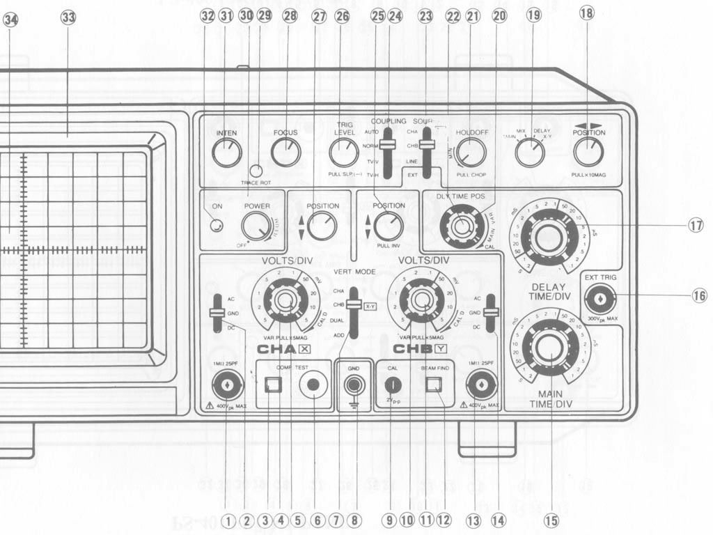
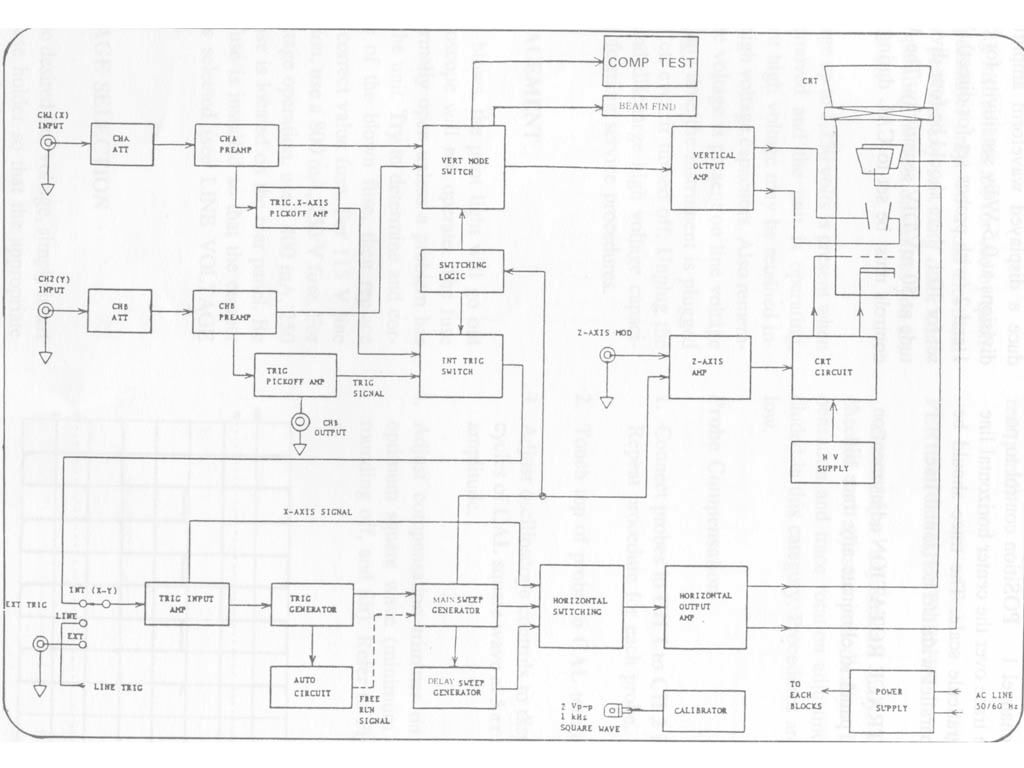
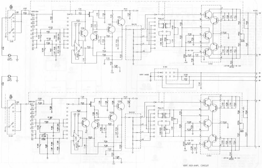
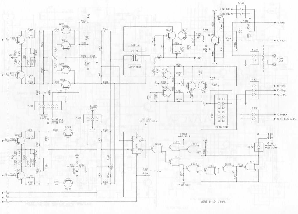
In the interest of staying on topic:rolleyes: , we discussed the oscope block diagram for the add function and how that was accomplished. When measuring the difference in 1-phase and 2-phase (see the way I stay on topic?) my scope has an add function. I have a block diagram and a schematic to go along with it if you are interested. See the pics below fpr the panel, complete block diagram, and the two parts of the vertical schematic. The vertical mode switch is in the middle of the part 1 schematic:

OscopeFront.jpg

OscopeBlockDiagram.jpg

OscopeVertSchemp1.jpg

OscopeVertSchemp2.jpg
 

engy

Senior Member
Location
Minnesota
Looks like we lost the OP after the first day.
Is there any way we can force grantcool to read the entire thread?:mad: :D
I wonder if we answered his question?:-?
 
Status
Not open for further replies.
Top