Sizing a Wire Trough Correctly?

Status
Not open for further replies.

EMCelec

Member
Location
VA
Need a little help, I have a trough sizing question. I have a 8' long horizontal trough leaving the side of a 1200a service switch for future tenant panels and 2 that I will be installing. I believe I am interpreting the code correctly and want to make sure that I am.

The wireway will consist of 4 sets of 350mcm copper conductors extending from the switch through the trough. Off of that I will have a 400a and 200 tap. (400a panel tap will be made with 4-3/0 and 1 # 3 ground; 200a panel tap to trough will be made with 4-3/0 and 1 #6 ground)

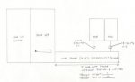
Am I correct that I can use a 12"x12" trough? That seems small, If so I would likely upsize but I want to check with you guys on the code part first.

Article 366.56(a) states taps and splices are permitted with gutters where they are accessible by means of removable covers or doors. The conductors, including splices and taps, shall not fill the gutter to more than 75% of its area.

4-350's x 16
13- 3/0's
1#6

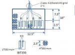
The Burndy UniTaps (BIBS350-8) I will be using are 7.68"x2.32"x2.50"

THERE ARE 2 ATTACHMENTS here both are the same file one is just a pdf vs. a png

Any help and direction that can be provided to help make sure I am interpreting correctly would be appreciated.

Thanks in advance,
EC
 

Attachments

  • Sizing Wire Troughs Mike Holt Forum Question.jpg
    Sizing Wire Troughs Mike Holt Forum Question.jpg
    9.6 KB · Views: 128
  • Sizing Wire Troughs Mike Holt Forum Question.pdf
    129.1 KB · Views: 122

Smart $

Esteemed Member
Location
Ohio
Before getting into gutter sizing, I think we need to discuss a problem with your design... :blink:

With parallel conductors (4 sets) coming off the SDM, you have to tap each set. Otherwise, you will create a tapping-a-tap scenario.

If you don't understand what I mean, let's take the 200A panel taps as an example. There is only one set going to the panel. Each conductor of that set will have to tap the corresponding circuit conductor of all four sets from the SDM. For a dead end tap using the type you spec'd, you'd need a 5-entry splice block for each line conductor.

For a non-dead-end tap, such as the 400A panel, you'd need a 10-entry block... 4-in, 2-tap, and 4-out.

My suggestion would be to see if you can find either an 8-hole lug, or a 4-hole lug rated for two-wires per hole (perhaps a daunting task???), in the SDM, and forget about tapping in the gutter. Just run the taps from the SDM lugs.
 
Last edited:

EMCelec

Member
Location
VA
First, not my design...this is on the approved drawings from the electrical engineer. (Not that that makes it right) however I don't see an issue with taking 4 phase conductors from the SDM into 1 single 8 port UniTap. 4 sets from SDM to Wire Trough plus 2 panel feeders (1 with a parallel set) = 7 which means there would be one spare port on the unitap for a future panel add above the wire trough..... Did you miSs read my post? Thanks for the comments, anyone have any comments about the original question on sizing a wire trough?

Thanks,
EC
 

Smart $

Esteemed Member
Location
Ohio
...Did you miSs read my post?...
No.... but I did misunderstand how how you intended to make the taps. :p When I first looked up the unitaps I inadvertently didn't copy the -8 suffix and all that was shown was a 3-entry block. :slaphead:

FWIW, the 75% area is cross sectional area as measured at any one cross section. Keep in mind that the tap block counts towards area fill also. You'll likely have to stagger the blocks.

The Burndy Unitaps are one-sided entry. If hell bent on using them, you should turn the unitaps so conductors do a Y turn, in to out. If the 350's go straight into the unitaps, the tap conductors will have to do a U-turn, thus counting twice towards cross section fill. You'd get a much cleaner install if you used dual entry tap block (wire can enter from either side). Also remember to alternate between line and load with adjacent entries.


I'll leave the sizing calculation to you... :happyyes:
 
Last edited:

cadpoint

Senior Member
Location
Durham, NC
I've been told that I've called things that they are are not, in the trade!

This is the same case, the word trough doesn't appear in the Index.
The NEC doesn't reconigize the term.

You are calling your equipment three different things throughout your post,
I can see your confusion!

It is either as you stated Article 366 an Auxiliary Gutter, or a Wireway(s), Metal
Article 376, Wireway(s), Nonmetallic, Article 378.

The other problem you might run into is that any panel(s) front edge can't
be beyond a gutter or wireway front edge, as well as disconnects!
So there will be no reach over... sorry couldn't find this article on short notice.
 
Last edited:

Smart $

Esteemed Member
Location
Ohio
...

The other problem you might run into is that any panel(s) front edge can't
be beyond a gutter or wireway front edge, as well as disconnects!
So there will be no reach over... sorry couldn't find this article on short notice.
110.26(A)(3), second and last sentence.
 

EMCelec

Member
Location
VA
"The other problem you might run into is that any panel(s) front edge can't
be beyond a gutter or wireway front edge, as well as disconnects!
So there will be no reach over... sorry couldn't find this article on short notice. "

NO, NO PROBLEM at all because I know how to use strut to build the panel out to the front of the trough...also no one seems to be helping me with my question, without the size of the trough how can you be sure the panel will extend past the face of the wireway/gutter/whatchamacallit? lol #sarcasm


ANYWAYS, back to the original question. Who wants to show the proper math and the size gutter/wireway per the NEC?
 

Strathead

Senior Member
Location
Ocala, Florida, USA
Occupation
Electrician/Estimator/Project Manager/Superintendent
I've been told that I've called things that they are are not, in the trade!

This is the same case, the word trough doesn't appear in the Index.
The NEC doesn't reconigize the term.

You are calling your equipment three different things throughout your post,
I can see your confusion!

It is either as you stated Article 366 an Auxiliary Gutter, or a Wireway(s), Metal
Article 376, Wireway(s), Nonmetallic, Article 378.

The other problem you might run into is that any panel(s) front edge can't
be beyond a gutter or wireway front edge, as well as disconnects!
So there will be no reach over... sorry couldn't find this article on short notice.

This reminds me of a recent complaint I have with probably the most respected (and I mean this respectfully) Electrical Engineer in my area. Their plans called for "NMC run under the 1st floor...) I told him, that he was asking for Romex, even though I knew he didn't mean it. He stated, with typical EE arrogance, "No, I am calling for non-metallic conduit." I wisely let it go, since I won the job anyway. Ironically though, his specs use RNC for schedule 40 in the specs. Imagine that?
 

kwired

Electron manager
Location
NE Nebraska
"The other problem you might run into is that any panel(s) front edge can't
be beyond a gutter or wireway front edge, as well as disconnects!
So there will be no reach over... sorry couldn't find this article on short notice. "

NO, NO PROBLEM at all because I know how to use strut to build the panel out to the front of the trough...also no one seems to be helping me with my question, without the size of the trough how can you be sure the panel will extend past the face of the wireway/gutter/whatchamacallit? lol #sarcasm


ANYWAYS, back to the original question. Who wants to show the proper math and the size gutter/wireway per the NEC?
I've calculated conductor fill before - about the same thing as raceway fill but with different percentage fill allowed.

Never calculated fill of splicing devices, but unless you tried to splice all three phases in the same cross sectional space you are not all that likley to take up too much space - you generally will need to stagger the splices and it usually results in easier access to them anyway.
 

Strathead

Senior Member
Location
Ocala, Florida, USA
Occupation
Electrician/Estimator/Project Manager/Superintendent
I've calculated conductor fill before - about the same thing as raceway fill but with different percentage fill allowed.

Never calculated fill of splicing devices, but unless you tried to splice all three phases in the same cross sectional space you are not all that likley to take up too much space - you generally will need to stagger the splices and it usually results in easier access to them anyway.

Was waiting for someone smarter than me to answer, but here goes. First, refer to article 312. Specifically table 312.6 (A) and 312.6(B) That is what you really need to size your gutter, and many people fail to use this.

All of that said, a 4x4 wireway has a 16 square inch cross section 20% (max fill of any cross section) is 3.2 square inches. 350 THHN has an area of .5242 square inches per table 5 in the back of the NEC. So 16 of them equals 8.3872 square inches. Not to be condescending, but the rest of it is math. Any of us trying to size these things should be capable of doing that. Look up the area of each conductor size in the tables, multiply by the number of conductors, add them for a total, multiply by 5 (5 x 20% fill) and then you have the minimum cross sectional area of your wireway.
 

kwired

Electron manager
Location
NE Nebraska
Was waiting for someone smarter than me to answer, but here goes. First, refer to article 312. Specifically table 312.6 (A) and 312.6(B) That is what you really need to size your gutter, and many people fail to use this.

All of that said, a 4x4 wireway has a 16 square inch cross section 20% (max fill of any cross section) is 3.2 square inches. 350 THHN has an area of .5242 square inches per table 5 in the back of the NEC. So 16 of them equals 8.3872 square inches. Not to be condescending, but the rest of it is math. Any of us trying to size these things should be capable of doing that. Look up the area of each conductor size in the tables, multiply by the number of conductors, add them for a total, multiply by 5 (5 x 20% fill) and then you have the minimum cross sectional area of your wireway.

In general if you size the wire way for needed wire bending space you will never end up with 4x4 wireway with 350kcmil conductors in it, unless you only made entries at the two walls with the longest dimension between them (the "ends").
 

Strathead

Senior Member
Location
Ocala, Florida, USA
Occupation
Electrician/Estimator/Project Manager/Superintendent
In general if you size the wire way for needed wire bending space you will never end up with 4x4 wireway with 350kcmil conductors in it, unless you only made entries at the two walls with the longest dimension between them (the "ends").
I agree wasn't implying that he would, was using to represent the math for cross section.
 

Smart $

Esteemed Member
Location
Ohio
In general if you size the wire way for needed wire bending space you will never end up with 4x4 wireway with 350kcmil conductors in it, unless you only made entries at the two walls with the longest dimension between them (the "ends").
Largest wire is 350kcmil. At most, one wire per terminal. Required minimum wire bending space is at least 5".

However, one of the main considerations is to not have to bend the 350's into a terminal. :happyyes:

Burndy BIBS350-8 is 7.68" in length. Gutter must be at least 8" in mounted height. If the install is also to permit future taps, I think the installer needs to leave more than one extra hole. I would go with at least a 10-entry block. Burndy BIBS350-10 is 9.50" in length. Burndy BIBS350-12 is 11.32" in length.

As mentioned earlier, I would go with double-sided entry blocks, avoiding u-turn with tap conductors.
http://www.polarisconnectors.com/pdfs/NSi/IPLD_series.pdf
 

Julius Right

Senior Member
Occupation
Electrical Engineer Power Station Physical Design Retired
I don?t think you need Burndy UniTaps (BIBS350-8) but only BIT350.In order to supply two sets of 4*3/0 [two conductors per each phase and neutral] from 4*350 mcm[one conductor per phase ] you need 4 uni taps [since all the enters are short-circuited with the same busbar then you need one uni tap per phase].BIT350 is provided with 2 enters and 2outlets.
The attached sketch shows one of possibilities.
 

Attachments

  • Cable Trough.jpg
    Cable Trough.jpg
    14.6 KB · Views: 45

Smart $

Esteemed Member
Location
Ohio
I don?t think you need Burndy UniTaps (BIBS350-8) but only BIT350.In order to supply two sets of 4*3/0 [two conductors per each phase and neutral] from 4*350 mcm[one conductor per phase ] you need 4 uni taps [since all the enters are short-circuited with the same busbar then you need one uni tap per phase].BIT350 is provided with 2 enters and 2outlets.
The attached sketch shows one of possibilities.
It's 4 sets of 4-350kcmil... 4 conductors per phase and neutral. All must be connected on load end for them to be parallel. Otherwise you'd be tapping a tap conductor... which is not permitted.

What I'm interested in is the available options for the SDM. If busbar-type load terminals are furnished or available (I think a fairly common option in 1200A gear), could simply take the feeder taps directly from panels back to the SDM, use compression terminations and bolt to the busbar terminals. Also, the trough could be substantially smaller.
 

Julius Right

Senior Member
Occupation
Electrical Engineer Power Station Physical Design Retired
If total rated current is 1200 A and the actual 2 panels are 400 A and 200 A the remaining 600 A
may be divided between the future 2 panels as 600 A and 0 A.
No one needs more than 2*350 mcm for 600 A.
However it will be necessary in the future not now.
In my opinion you may connect only the 2 panel now installed each individually connected.
 

Attachments

  • cable trough connections.jpg
    cable trough connections.jpg
    26.4 KB · Views: 21

Smart $

Esteemed Member
Location
Ohio
If total rated current is 1200 A and the actual 2 panels are 400 A and 200 A the remaining 600 A
may be divided between the future 2 panels as 600 A and 0 A.
No one needs more than 2*350 mcm for 600 A.
However it will be necessary in the future not now.
In my opinion you may connect only the 2 panel now installed each individually connected.
While I can't make sense of your diagram, I believe we are nearly on the same page. :cool:

I'm saying you don't need 350's at all. Run 3/0's from SDM (1200A switch)... 2 sets for the 400A panel, 1 set for the 200A panel. The only question is how to connect in the SDM....

Use the following as an example:
Ge-disconnect-TC72368-1200A-600V-3P-fused-indoor-picture-2.jpg
Replace the one-hole mechanical lugs on load side with two-hole lugs sized to accept 3/0's... or simply use compression lugs.
 

kwired

Electron manager
Location
NE Nebraska
I don?t think you need Burndy UniTaps (BIBS350-8) but only BIT350.In order to supply two sets of 4*3/0 [two conductors per each phase and neutral] from 4*350 mcm[one conductor per phase ] you need 4 uni taps [since all the enters are short-circuited with the same busbar then you need one uni tap per phase].BIT350 is provided with 2 enters and 2outlets.
The attached sketch shows one of possibilities.

First the BIT series are two port units - there are 4 access holes - two for conductors, two for set screw access.

The 4 - 350mcm are not a parallel set with a higher ampacity if they are not joined at both ends to effectively make them one conductor. If you do it this way you started your "tap" at the source end. Even if you do not exceed the applicable tap length limit, you can not tap it again, the first tap must end at an overcurrent device to comply with the tap rules.
 

Julius Right

Senior Member
Occupation
Electrical Engineer Power Station Physical Design Retired
The actual solution complies with NEC if we intend to use only one circuit breaker of 1200 A.
It will be 16 cables of 350 mcm all along the trough,
there will be 16 uni taps and 128 connectors [8 per unitap] of 350 MCM and other of 3/0.
If we use [for now] 2 breakers of 400 A respective 200 A and for the future extension we will keep only 2 places for two 600 A breakers no need for any connectors and all the cable could be 3/0-as Smart$ said. The trough has to accommodate 8*4 [or 10*4] 3/0 cables only. In any case minimum 30?*10? in actual solution and 20?*6? in the last solution will be the trough dimensions.
 
Status
Not open for further replies.
Top