JFletcher
Senior Member
- Location
- Williamsburg, VA
What would you use 480V on that only would be supplied by two legs?
480V lighting.
~~~~~~~~~~~~~~~~~
The model #, job# and serial# of the xfmr is the same in both pics; they are of the same unit.
~~~~~~~~~~~~~~~~~
This link:
http://federalpacific.com/training/transformer-basics/chapter-2.htm
may help as might this one:
https://stevenengineering.com/tech_support/PDFs/55MAIN.pdf
which says an xfmr this size can be reverse fed.
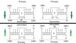
winnie, where is the high side center tap? I dont see it and the schematic appears to show one primary/high side coil and two secondaries/low side the latter of which can be wired series or parallel.
like infinity I'm just not seeing how one could get 240 and 480 simultaneously from the high side
")